-
 +84 982 384 688 - Mr. Thi | +84 982 803 586- Ms. Hoa
 -
 theptangiabao@gmail.com
 -
 Thứ 2 - Thứ 7 | 07:30 - 17:00
English

 Home
HomeElectric-Fusion-Welded Steel Pipe, A671 Grade CF 71
 Product info
| Supplier: | Tapgroup internation.,JSC |
| Address: | Số 32 Lô N4D, đường X2A, Yên Sở, Hoàng Mai, Hà Nội |
| Phone: | 0084 933 86 77 86 |
| Email: | info@tapgroup.vn |
| Website: | https://supplier-pipe-tube-ongthep.com |
| Insurance: | 12 tháng |
| Status: | Mới 100% |
| Origin: | China, Korea, Malaysia, Thailand, Japan, EU, G7 |
| Name | Electric-Fusion-Welded Steel Pipe, A671 Grade CF 71 | |||||||
| Type Of Pipe | Electric-Fusion-Welded Steel Pipe | EFW Pipe | ||||||
| Electric-Fusion-Welded Steel Pipe, A671 Grade CF 71 | EFW Pipe A671 Grade CF 71 | |||||||
|
Standard Specification for Electric-Fusion-Welded Steel Pipe for Atmospheric and Lower Temperatures |
||||||||
| Plate specifications | ||||||||
| Pipe grade | Type of steel | ASTM specification | ||||||
| No. | Grade | |||||||
| CF 71 | nickel steel | A 203/A 203M | E | |||||
| Heat treatment parameters | ||||||||
| Pipe grade | ASTM specification and grade |
Post weld heat treatment temperature range °F (°C) |
Normalizing temperature, max, °F (°C) |
Quenching temperature, max, °F, (°C) |
Quenching temperature, min, °F, (°C) |
Precipitation heat treatment temperature range °F (°C) |
||
| CF 71 | A 203/A 203M (E) | 1100-1175 (590-635) | 1750 (950) | … | … | … | ||
| ANumber indicate minimum tensile strength in ksi. | ||||||||
| BIn no case shall be the post-weld heat-treatment temperature exceed the mill tempering temperature. | ||||||||
| CTempering range 1100 to 1300 (590 to 705), if accelerated cooling ultilized per specification A516/a 516M. | ||||||||
| DPer ASME Section VIII specification A 517/A 517M specified 1650 (900) minimum quenching temperature. | ||||||||
| Wall Thickness: Welded and Seamless Wrought Steel Pipe, ANSI /ASME B36.10M | ||||||||
| Schedule (SCH) | SCH 5 | SCH 10 | SCH 20 | SCH 30 | SCH STD | SCH 40 | SCH 60 | SCH XS |
| SCH 80 | SCH 100 | SCH 120 | SCH 160 | SCH XXS | SCH XX.H | |||
| End of pipe end | ||||||||
| Plain Ends (PE) | The PE pipes will generally be used for the smaller diameters pipe systems and in combination with Slip On flanges and Socket Weld fittings and flanges. | |||||||
| Threaded Ends (TE) | The TE implementation speaks for itself, this performance will generally used for small diameters pipe systems, and the connections will be made with threaded flanges and threaded fittings. | |||||||
| Beveled Ends (BE) | The BE implementation is applied to all diameters of buttweld flanges or buttweld fittings, and will be directly welded (with a small gap 3-4 mm) to each other or to the pipe. Ends are mostly be beveled to angle 30° (+ 5° / -0°) with a root face of 1.6 mm (± 0.8 mm). | |||||||
| Grooved ends | (example Victaulic pipes): these are pipes that allow a quick connection, used for non-critical applications | |||||||
| Threaded and coupled ends |
(T&C), generally used for gas distribution, Threaded connections are the most common pipe fittings used in oil and gas transportation systems. Due to external vibrations, cyclic loads, and pollution, the fitting parts may start getting loose, which could result in pipeline leaks and other environmental disasters. It is of great significance to develop a reliable technique that could provide… |
|||||||
| Type end : Plain Ends / Beveled Ends: Pipe | ||||||||
|
• Bevel End (BE) • Bevel Both Ends (BBE) • Bevel Large End (BLE) • Bevel One End (BOE) • Bevel Small End (BSE) • Bevel for Welding (BFW) • Buttweld End (BE) |
• End of Pipe (EOP) • Flange One End (FOE) • Plain End (PE) • Plain Both Ends (PBE) • Plain One End (POE) • Thread End (TE) • Thread Both Ends (TBE) |
• Thread Large End (TLE) • Thread One End (TOE) • Thread Small End (TSE) • Threads Only (TO) • Threads per Inch (TP I) |
||||||
| Plastic End Caps for Tubing and Pipe Ends | ||||||||
| Pipe End Caps | Pipe End Plugs | Threaded Pipe Caps | Threaded Pipe Plugs | |||||
| The American Society Of Mechanical Engineers | American National Standards Institute | |||||||
| ASME B36.19M | ANSI B36.19 | |||||||
| ASME B36.10M | ANSI B36.10 | |||||||
| Product related keywords | |
| Electric-Fusion-Welded Steel Pipe for Atmospheric and Lower Temperatures A671 Grade CF 71 | |
| Electric-Fusion-Welded Steel Pipe, A671 Grade CF 71 | EFW Pipe, A671 Grade CF 71 |
| Electric-Fusion-Welded Steel Pipe, A671 Grade CF 71, SCH 5 | Electric-Fusion-Welded Steel Pipe, A671 Grade CF 71, SCH 10 |
| Electric-Fusion-Welded Steel Pipe, A671 Grade CF 71, SCH 20 | Electric-Fusion-Welded Steel Pipe, A671 Grade CF 71, SCH 30 |
| Electric-Fusion-Welded Steel Pipe, A671 Grade CF 71, SCH STD | Electric-Fusion-Welded Steel Pipe, A671 Grade CF 71, SCH 40 |
| Electric-Fusion-Welded Steel Pipe, A671 Grade CF 71, SCH 60 | Electric-Fusion-Welded Steel Pipe, A671 Grade CF 71, SCH XS |
| Electric-Fusion-Welded Steel Pipe, A671 Grade CF 71, SCH 80 | Electric-Fusion-Welded Steel Pipe, A671 Grade CF 71, SCH 100 |
| Electric-Fusion-Welded Steel Pipe, A671 Grade CF 71, SCH 120 | Electric-Fusion-Welded Steel Pipe, A671 Grade CF 71, SCH 160 |
| Electric-Fusion-Welded Steel Pipe, A671 Grade CF 71, SCH XXS | Electric-Fusion-Welded Steel Pipe, A671 Grade CF 71, SCH 160 |
| Coated and Lined Pipe | |||||
| Electric-Fusion-Welded Steel Pipe for Atmospheric and Lower Temperatures A671 Grade CF 71 | |||||
|
External FBE Coating Pipe (Pipe PP) – Pipe PE Pipe Epoxy (FBE) |
Fusion Bonded Epoxy (FBE) coating protects pipe surfaces against corrosion. Double or triple layers of FBE may even increase the resistance to friction and abrasion. FBE coating is also used as the primer layer in 3-layer PE/PP coating systems. Electrostatic epoxy powder is sprayed onto a pipe at a temperature typically around 220 – 235°C. On reaching the hot pipe surface, the epoxy powder melts and forms an uniform layer of epoxy coating on the pipe. |
||||
|
3 Layer PP/PE Coating Pipe (Pipe FBE ) – ( Pipe PE/PP layer |
In addition to an anti-corrosion layer of FBE coating, mechanical protection can be added by applying a layer of Polyethylene (PE) or Polypropylene (PP). An adhesive layer takes care of the bonding between the FBE and PE/PP layer. Granules of PE/PP are extruded onto the passing pipe, forming a solid coating layer. Side extrusion is most commonly used, where a sheet of PE/PP is wrapped around a pipe. For smaller diameter pipes, so-called sleeve/ring extrusion is a common process. |
||||
|
External Liquid Coating Pipe (Pipe PU) |
With external liquid coating, coating is applied to the outside pipe surface by a spraying system, providing corrosion protection for the pipe surfaces. There are multiple coating types available e.g. liquid epoxy, polyurethane (PU), or e.g. (UV-curable) laquer. | ||||
|
Internal Liquid Lining Pipe polyurethane (PU), or 2-component coating. |
Internal liquid lining is a coating layer on an internal pipe surface to protect against corrosion or to optimize flow efficiency. There are multiple coating types available such as liquid epoxy, polyurethane (PU), or 2-component coating. After placing the pipe in the internal liquid coating station, the pipe ends are sealed off and a lance with the spraying gun system is moved through the pipe. Pre-heating could be an option for internal liquid coating. |
||||
|
Internal FBE Lining Pipe Fusion Bonded Epoxy (FBE) |
An internal FBE coating is used to protect the inner surfaces of steel pipes from the influence of corrosion and light mechanical impacts and it provides excellent resistance to cathodic disbondment. The internal Fusion Bonded Epoxy (FBE) system is based on an epoxy powder spray system, mounted on a lance. The lance moves through the pipe while the epoxy powder is sprayed onto the internal pipe surface. The pipe must be heated so that the epoxy powder melts onto the pipe. After FBE application, the layer requires curing. |
||||
|
Cement Mortar Lining (CML) Pipe |
Cement Mortar Lining (CML) is a method for applying a mixture of sand, cement and water onto internal pipe surfaces using a centrifugal spinning or pooring method. A smooth and compact layer of cement mortar protects water pipes against corrosion and abrasion. A characteristic of CML is that blasting the pipe surfaces is not necessarily required prior to the CML application. Selmers has solutions for factory applied and in-situ applied CML. |
||||
|
Concrete Weight Coating 3LPE/PP-coated Pipe |
During the concrete weight coating process, concrete is applied onto the pipe. The concrete layer adds additional weight to pipes to compensate the buoyancy of submarine pipelines, and it also provides protection from external influences. Impingement: 3LPE/PP-coated pipes with weld cage or wire mesh reinforcement. Concrete is sprayed at the pipe by high speed application drums. Compression: FBE or 3LPE/PP coated pipes with concrete wrapped around the pipe along with wire mesh reinforcement. |
||||
|
PU Foam Coating polyurethane foam (PUF) Pipe |
To keep substances in a pipeline at the correct temperature, polyurethane foam (PUF) insulation coating is commonly used for hot oil transmission lines as well as in district heating and cooling. Pipe-in-pipe application consists of an inner pipe and an outer jacket; the space between them is filled with PUF. Another manner for applying PUF is spraying PUF onto a rotating pipe, with an optional extra mechanical protection layer. |
||||
|
PP Foam Coating Multi-layer coating with polypropylene (PP) Pipe |
Multi-layer coating with polypropylene (PP) foam providing high thermal insulation; this is used for deepwater pipeline projects. In some cases glass synthetic PP (PP enforced with glass fibre spheres) is used instead of PP foam. On top of a 3-layer PP coating, various layers of PP foam ensure a pipe gets the insulating characteristics required. Finally, mechanical protection is added with a solid top layer of PP. |
||||
| Material Lined Pipe / Lining Pipe | |||||
| Teflon (PTFE) Lined Pipe | Teflon (PTFE) Lining Pipe | Cement mortar Lined Pipe | |||
| Cement mortar Lining Pipe | Liquid epoxy Lined Pipe | Liquid epoxy Lining Pipe | |||
| Glass Lined Pipe | Glass Lining Pipe | Fusion bonded epoxy (FBE) Lining Pipe | |||
| Fusion bonded epoxy (FBE) Lined Pipe | Polyethylene Lining Pipe | Bituminous asphalt Lined Pipe | |||
| Polyethylene Lined Pipe | Bituminous asphalt Lining Pipe | bitum Lined Pipe | |||
| bitum Lining Pipe | Zinc Lined Pipe | Zinc Lining Pipe | |||
| galvanized Lined Pipe | galvanized Lining Pipe | PFA-Lined Pipe | |||
| PFA Lining Pipe | Rubber Lined Pipe | NRB Lined Pipe | |||
| Rubber Lining Pipe | NRB Lining Pipe | Polypropylene (PP) Lined Pipe | |||
| Polypropylene (PP) Lining Pipe | Ethylene tetraflurorethylene Lined Pipe | Ethylene tetraflurorethylene Lining Pipe | |||
| ETFE Lined Pipe | ETFE Lining Pipe | polytetrafluroethylene Lined Pipe | |||
| polytetrafluroethylene Lining Pipe | Polyvinylidene Fluoride Lined Pipe | PVDF Lining Pipe | |||
| Polyvinylidene Fluoride Lining Pipe | Perfluoroalkoxy alkane Lined Pipe | PVDF Lined Pipe | |||
| Fluorinated ethylene propylene Lined Pipe | Fluorinated ethylene propylene Lining Pipe | ||||
| EFP Lined Pipe | EFP Lining Pipe | ||||
| Pipe Coating ( Coated Pipes) | |||||
| Three-layer Polyethylene (3LPE) Pipe | 3 layers Polypropylene (3LPP) Pipe | Epoxy | |||
| Polypropylene (PUR) Pipe | Fusion Bonded Epoxy (FBE) Pipe | pickl. | |||
| 3-Layer Polyolefin Coatings | Asphalt enameled and polyurethane (PUR) Pipe | soaked in oil | |||
| 2-Layer Polyolefin Coatings | Fusion Bonded and Liquid Bonded Epoxy, pipe | galvanized | |||
| Fusion Bonded Epoxy Coating | 1-Layer Polyolefin Coatings | 3 Layer PP/PE Coating | |||
| 3 LPE (External 3 Layer Polyethylene) |
Flow Efficiency Coatings for gas pipelines Liquid Epoxy Coatings for water pipelines |
pickled | |||
| 3 LPP (External 3 Layer Polypropylene) | FBE (External Fusion Bonded Epoxy | External Liquid Coating | |||
| Internal Liquid Lining | External FBE Coating | Internal FBE Lining | |||
| Cement Mortar Lining | Concrete Weight Coating | PU Foam Coating | |||
| Black Coated | PP Foam Coating | phosphated | |||
| zinc coated | hot dipped galvanized | hot-dipped zinc-coated | oiled and plugged | ||
| pickled and oiled | cold galvanized | external protection | |||
| Dimensions of Steel Pipes ASME B36.10 and B36.19 | ||||||
| Electric-Fusion-Welded Steel Pipe for Atmospheric and Lower Temperatures ASTM A671 Grade CF 71 | ||||||
| 1/2 inches to 2 inches | ||||||
| NPS | 1/2" | 3/4" | 1" | 1¼" | 1½" | 2" |
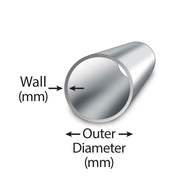
| OD | 21.3 | 26.7 | 33.4 | 42.2 | 48.3 | 60.3 |
| Wall Thickness | ||||||
| Sch 5 | 1.65 | 1.65 | 1.65 | 1.65 | 1.65 | 1.65 |
| Sch 5S | 1.65 | 1.65 | 1.65 | 1.65 | 1.65 | 1.65 |
| Sch 10 | 2.11 | 2.11 | 2.77 | 2.77 | 2.77 | 2.77 |
| Sch 10S | 2.11 | 2.11 | 2.77 | 2.77 | 2.77 | 2.77 |
| Sch 20 | – | … | – | … | – | … |
| Sch 30 | 2.41 | 2.41 | 2.90 | 2.97 | 3.18 | 3.18 |
| STD | 2.77 | 2.87 | 3.38 | 3.56 | 3.68 | 3.91 |
| Sch 40 | 2.77 | 2.87 | 3.38 | 3.56 | 3.68 | 3.91 |
| Sch 40S | 2.77 | 2.87 | 3.38 | 3.56 | 3.68 | 3.91 |
| Sch 60 | – | … | – | … | – | … |
| XS | 3.73 | 3.91 | 4.55 | 4.85 | 5.08 | 5.54 |
| Sch 80 | 3.73 | 3.91 | 4.55 | 4.85 | 5.08 | 5.54 |
| Sch 80S | 3.73 | 3.91 | 4.55 | 4.85 | 5.08 | 5.54 |
| Sch 100 | – | … | – | … | – | … |
| Sch 120 | – | … | – | … | – | … |
| Sch 140 | – | … | – | … | – | … |
| XXS | 7.47 | 7.82 | 9.09 | 9.70 | 10.15 | 11.07 |
| Sch 160 | 4.78 | 5.56 | 6.35 | 6.35 | 7.14 | 8.74 |
| NPS = Nominal Pipe Size O.D. = Outside Diameter | ||||||
| Dimensions are in millimeters unless otherwise indicated. | ||||||
| DIMENSIONAL TOLERANCES FOR SEAMLESS AND WELDED PIPES ASTM A530 | ||||||
| Nominal pipe size | ||||||
| up to 4 = ± 0.79 mm | 5 thru 8 = + 1.58 mm / – 0.79 mm | ||||||
| 10 thru 18 = + 2.37 mm / – 0.79 mm | 20 thru 24 = + 3.18 mm / – 0.79 mm | ||||||
| Wall Thickness | Length | Weight | ||||
| All Diameters = – 12.5% | + 6.40 mm / – 0 mm | Weight = + 10% / – 1.5% | ||||
| 2 1/2 inches to 5 inches | ||||||
| NPS | 2½" | 3" | 3½" | 4" | 5" | |
| OD | 73 | 88.9 | 101.6 | 114.3 | 141.3 | |
| Wall Thickness | ||||||
| Sch 5 | 2.11 | 2.11 | 2.11 | 2.11 | 2.77 | |
| Sch 5S | 2.11 | 2.11 | 2.11 | 2.11 | 2.77 | |
| Sch 10 | 3.05 | 3.05 | 3.05 | 3.05 | 3.40 | |
| Sch 10S | 3.05 | 3.05 | 3.05 | 3.05 | 3.40 | |
| Sch 20 | … | … | ||||
| Sch 30 | 4.78 | 4.78 | 4.78 | 4.78 | … | |
| STD | 5.16 | 5.49 | 5.74 | 6.02 | 6.55 | |
| Sch 40 | 5.16 | 5.49 | 5.74 | 6.02 | 6.55 | |
| Sch 40S | 5.16 | 5.49 | 5.74 | 6.02 | 6.55 | |
| Sch 60 | … | … | ||||
| XS | 7.01 | 7.62 | 8.08 | 8.56 | 9.53 | |
| Sch 80 | 7.01 | 7.62 | 8.08 | 8.56 | 9.53 | |
| Sch 80S | 7.01 | 7.62 | 8.08 | 8.56 | 9.53 | |
| Sch 100 | … | … | ||||
| Sch 120 | … | 11.13 | 12.7 | |||
| Sch 140 | … | … | ||||
| XXS | 14.02 | 15.24 | 17.12 | 19.05 | ||
| Sch 160 | 9.53 | 11.13 | 13.49 | 15.88 | ||
| NPS = Nominal Pipe Size O.D. = Outside Diameter | ||||||
| Dimensions are in millimeters unless otherwise indicated. | ||||||
| DIMENSIONAL TOLERANCES FOR SEAMLESS AND WELDED PIPES ASTM A530 | ||||||
| Nominal pipe size | ||||||
| up to 4 = ± 0.79 mm | 5 thru 8 = + 1.58 mm / – 0.79 mm | ||||||
| 10 thru 18 = + 2.37 mm / – 0.79 mm | 20 thru 24 = + 3.18 mm / – 0.79 mm | ||||||
| Wall Thickness | Length | Weight | ||||
| All Diameters = – 12.5% | + 6.40 mm / – 0 mm | Weight = + 10% / – 1.5% | ||||
| 6 inches to 14 inches | ||||||
| NPS | 6" | 8" | 10" | 12" | 14" | |
| OD | 168.3 | 219 | 273 | 323.9 | 355.6 | |
| Wall Thickness | ||||||
| Sch 5 | 2.77 | 2.77 | 3.40 | 3.96 | 3.96 | |
| Sch 5S | 2.77 | 2.77 | 3.40 | 3.96 | 3.96 | |
| Sch 10 | 3.40 | 3.76 | 4.19 | 4.57 | 6.35 | |
| Sch 10S | 3.40 | 3.76 | 4.19 | 4.57 | 4.78 | |
| Sch 20 | 6.35 | 6.35 | 6.35 | 7.92 | ||
| Sch 30 | 7.04 | 7.80 | 8.38 | 9.53 | ||
| STD | 7.11 | 8.18 | 9.27 | 9.53 | 9.53 | |
| Sch 40 | 7.11 | 8.18 | 9.27 | 10.31 | 11.13 | |
| Sch 40S | 7.11 | 8.18 | 9.27 | 9.53 | 9.53 | |
| Sch 60 | 10.31 | 12.70 | 14.27 | 15.06 | ||
| XS | 10.97 | 12.70 | 12.70 | 12.70 | 12.70 | |
| Sch 80 | 10.97 | 12.70 | 15.09 | 17.48 | 19.05 | |
| Sch 80S | 10.97 | 12.70 | 12.70 | 12.70 | 12.70 | |
| Sch 100 | 15.09 | 18.26 | 21.44 | 23.83 | ||
| Sch 120 | 14.27 | 18.26 | 21.44 | 25.40 | 27.79 | |
| Sch 140 | 20.62 | 25.40 | 28.58 | 31.75 | ||
| XXS | 21.95 | 22.23 | 25.40 | 25.40 | ||
| Sch 160 | 18.26 | 23.01 | 28.58 | 33.32 | 35.71 | |
| NPS = Nominal Pipe Size O.D. = Outside Diameter | ||||||
| Dimensions are in millimeters unless otherwise indicated. | ||||||
| DIMENSIONAL TOLERANCES FOR SEAMLESS AND WELDED PIPES ASTM A530 | ||||||
| Nominal pipe size | ||||||
| up to 4 = ± 0.79 mm | 5 thru 8 = + 1.58 mm / – 0.79 mm | ||||||
| 10 thru 18 = + 2.37 mm / – 0.79 mm | 20 thru 24 = + 3.18 mm / – 0.79 mm | ||||||
| Wall Thickness | Length | Weight | ||||
| All Diameters = – 12.5% | + 6.40 mm / – 0 mm | Weight = + 10% / – 1.5% | ||||
| 16 inches to 24 inches | ||||||
| NPS | 16" | 18" | 20" | 22" | 24" | |
| OD | 406.04 | 457.2 | 508 | 558.8 | 609.6 | |
| Wall Thickness | ||||||
| Sch 5 | 4.19 | 4.19 | 4.78 | 4.78 | 5.54 | |
| Sch 5S | 4.19 | 4.19 | 4.78 | 4.78 | 5.54 | |
| Sch 10 | 6.35 | 6.35 | 6.35 | 6.35 | 6.35 | |
| Sch 10S | 4.78 | 4.78 | 5.54 | 5.54 | 6.35 | |
| Sch 20 | 7.92 | 7.92 | 9.53 | 9.53 | 9.53 | |
| Sch 30 | 9.53 | 11.13 | 12.70 | 12.70 | 14.27 | |
| STD | 9.53 | 9.53 | 9.53 | 9.53 | 9.53 | |
| Sch 40 | 12.70 | 14.27 | 15.09 | … | 17.48 | |
| Sch 40S | 9.53 | 9.53 | 9.53 | … | 9.53 | |
| Sch 60 | 16.66 | 19.05 | 20.62 | 22.23 | 24.61 | |
| XS | 12.70 | 12.70 | 12.70 | 12.70 | 12.70 | |
| Sch 80 | 21.44 | 23.83 | 26.19 | 28.58 | 30.96 | |
| Sch 80S | 12.70 | 12.70 | 12.70 | … | 12.70 | |
| Sch 100 | 26.19 | 29.36 | 32.54 | 34.93 | 38.89 | |
| Sch 120 | 30.96 | 34.93 | 38.10 | 41.28 | 46.02 | |
| Sch 140 | 36.53 | 39.67 | 44.45 | 47.63 | 52.37 | |
| XXS | … | … | ||||
| Sch 160 | 40.49 | 45.24 | 50.01 | 53.98 | 59.54 | |
| NPS = Nominal Pipe Size O.D. = Outside Diameter | ||||||
| Dimensions are in millimeters unless otherwise indicated. | ||||||
| DIMENSIONAL TOLERANCES FOR SEAMLESS AND WELDED PIPES ASTM A530 | ||||||
| Nominal pipe size | ||||||
| up to 4 = ± 0.79 mm | 5 thru 8 = + 1.58 mm / – 0.79 mm | ||||||
| 10 thru 18 = + 2.37 mm / – 0.79 mm | 20 thru 24 = + 3.18 mm / – 0.79 mm | ||||||
| Wall Thickness | Length | Weight | ||||
| All Diameters = – 12.5% | + 6.40 mm / – 0 mm | Weight = + 10% / – 1.5% | ||||
| 26 inches to 48 inches | ||||||
| 26" > 48" | Wall Thickness and Weight | |||||
| NPS | OD | 5 | 5S | 10 | ||
| 26 | 660 | wt | 7.92 | |||
| kg/m | 127.36 | |||||
| 28 | 711 | wt | 7.92 | |||
| kg/m | 137.32 | |||||
| 30 | 762 | wt | 6.35 | 6.35 | 7.92 | |
| kg/m | 118.34 | 118.31 | 147.29 | |||
| 32 | 813 | wt | 7.92 | |||
| kg/m | 157.25 | |||||
| 34 | 864 | wt | 7.92 | |||
| kg/m | 167.21 | |||||
| 36 | 914 | wt | 7.92 | |||
| kg/m | 176.97 | |||||
| 38 | 965 | wt | ||||
| kg/m | ||||||
| 40 | 1016 | wt | ||||
| kg/m | ||||||
| 42 | 1067 | wt | ||||
| kg/m | ||||||
| 44 | 1118 | wt | ||||
| kg/m | ||||||
| 46 | 1168 | wt | ||||
| kg/m | ||||||
| 48 | 1219 | wt | ||||
| kg/m | ||||||
| 26 – 48 | Wall Thickness and Weight | |||||
| NPS | OD | 10S | 20 | 30 | ||
| 26 | 660 | wt | 12.70 | |||
| kg/m | 202.74 | |||||
| 28 | 711 | wt | 12.70 | 15.88 | ||
| kg/m | 218.71 | 272.23 | ||||
| 30 | 762 | wt | 7.92 | 12.70 | 15.88 | |
| kg/m | 132.91 | 234.68 | 292.20 | |||
| 32 | 813 | wt | 12.70 | 15.88 | ||
| kg/m | 250.65 | 312.17 | ||||
| 34 | 864 | wt | 12.70 | 15.88 | ||
| kg/m | 266.63 | 332.14 | ||||
| 36 | 914 | wt | 12.70 | 15.88 | ||
| kg/m | 282.29 | 351.73 | ||||
| 38 | 965 | wt | ||||
| kg/m | ||||||
| 40 | 1016 | wt | ||||
| kg/m | ||||||
| 42 | 1067 | wt | ||||
| kg/m | ||||||
| 44 | 1118 | wt | ||||
| kg/m | ||||||
| 46 | 1168 | wt | ||||
| kg/m | ||||||
| 48 | 1219 | wt | ||||
| kg/m | ||||||
| 26 – 48 | Wall Thickness and Weight | |||||
| NPS | OD | STD | 40 | XS | ||
| 26 | 660 | wt | 9.53 | 12.70 | ||
| kg/m | 152.88 | 202.74 | ||||
| 28 | 711 | wt | 9.53 | 12.70 | ||
| kg/m | 164.86 | 218.71 | ||||
| 30 | 762 | wt | 9.53 | 12.70 | ||
| kg/m | 176.85 | 234.68 | ||||
| 32 | 813 | wt | 9.53 | 17.48 | 12.70 | |
| kg/m | 188.83 | 342.94 | 250.65 | |||
| 34 | 864 | wt | 9.53 | 17.48 | 12.70 | |
| kg/m | 200.82 | 364.92 | 266.63 | |||
| 36 | 914 | wt | 9.53 | 19.05 | 12.70 | |
| kg/m | 212.57 | 420.45 | 282.29 | |||
| 38 | 965 | wt | 9.53 | 12.70 | ||
| kg/m | 224.56 | 298.26 | ||||
| 40 | 1016 | wt | 9.53 | 12.70 | ||
| kg/m | 236.54 | 314.23 | ||||
| 42 | 1067 | wt | 9.53 | 12.70 | ||
| kg/m | 248.53 | 330.21 | ||||
| 44 | 1118 | wt | 9.53 | 12.70 | ||
| kg/m | 260.52 | 346.18 | ||||
| 46 | 1168 | wt | 9.53 | 12.70 | ||
| kg/m | 272.70 | 361.84 | ||||
| 48 | 1219 | wt | 9.53 | 12.70 | ||
| kg/m | 284.25 | 377.81 | ||||
| NPS = Nominal Pipe Size | ||||||
| O.D. = Outside Diameter | ||||||
| WT = Walltickness | ||||||
| KG/M = Kilogram per meter | ||||||
| Dimensions are in millimeters unless otherwise indicated | ||||||
| Weights are in kilograms p/meter and approximately given | ||||||
-
Electric-Fusion-Welded Steel Pipe, A671 Grade CP 75
-
Electric-Fusion-Welded Steel Pipe, A671 Grade CP 65
-
Electric-Fusion-Welded Steel Pipe, A671 Grade CK 75
-
Electric-Fusion-Welded Steel Pipe, A671 Grade CJ 113
-
Electric-Fusion-Welded Steel Pipe, A671 Grade CJ 112
-
Electric-Fusion-Welded Steel Pipe, A671 Grade CJ 111
-
Electric-Fusion-Welded Steel Pipe, A671 Grade CJ 110
-
Electric-Fusion-Welded Steel Pipe, A671 Grade CJ 109
-
Electric-Fusion-Welded Steel Pipe, A671 Grade CJ 108
-
Electric-Fusion-Welded Steel Pipe, A671 Grade CJ 107
-
Electric-Fusion-Welded Steel Pipe, A671 Grade CJ 106
-
Electric-Fusion-Welded Steel Pipe, A671 Grade CJ 105
-
Electric-Fusion-Welded Steel Pipe, A671 Grade CJ 104
-
Electric-Fusion-Welded Steel Pipe, A671 Grade CJ 103
-
Electric-Fusion-Welded Steel Pipe, A671 Grade CJ 102
-
Electric-Fusion-Welded Steel Pipe, A671 Grade CJ 101
-
Electric-Fusion-Welded Steel Pipe, A671 Grade CH 100
-
Electric-Fusion-Welded Steel Pipe, A671 GradeCG 100
-
Electric-Fusion-Welded Steel Pipe, A671 Grade CF 66
-
Electric-Fusion-Welded Steel Pipe, A671 Grade CF 70
-
Electric-Fusion-Welded Steel Pipe, A671 Grade CF 65
-
Electric-Fusion-Welded Steel Pipe, A671 Grade CD 80
-
Electric-Fusion-Welded Steel Pipe, A671 Grade CD 70
-
Electric-Fusion-Welded Steel Pipe, A671 Grade CC 70
-
Electric-Fusion-Welded Steel Pipe, A671 Grade CC 65
-
Electric-Fusion-Welded Steel Pipe, A671 Grade CC 60
-
Electric-Fusion-Welded Steel Pipe, A671 Grade CB 70
-
Electric-Fusion-Welded Steel Pipe, A671 Grade CB 65
-
Electric-Fusion-Welded Steel Pipe, A671 Grade CB 60
-
Electric-Fusion-Welded Steel Pipe, A671 Grade CA 55

Mr. Thi
 Email:
theptangiabao@gmail.com
Email:
theptangiabao@gmail.com
|
 Skype:
|
 Hotline/ Zalo/ Wechat:
+84 982 384 688
Hotline/ Zalo/ Wechat:
+84 982 384 688
|

Ms. Hoa
|
Email:
theptangiabao@gmail.com
|
|
Skype:
|
|
Hotline/ Zalo/ Wechat:
+84 982 803 586
|

Ms. Phương
|
Email:
theptangiabao@gmail.com
|
|
Skype:
|
|
Hotline/ Zalo/ Wechat:
+84 971 567 341
|

Ms. Trinh
|
Email:
theptangiabao@gmail.com
|
|
Skype:
|
|
Hotline/ Zalo/ Wechat:
+84 971 567 943
|

Ms. Trân
|
Email:
theptangiabao@gmail.com
|
|
Skype:
|
|
Hotline/ Zalo/ Wechat:
+84 971 567 954
|
![]() HỒ CHÍ MINH CN1
HỒ CHÍ MINH CN1
Trụ Sở Hồ Chí Minh
Address : Số 8 đường số 20, P. Bình Hưng Hoà, Q. Bình Tân, TP. HCM
Phone : +84 982 384 688 - Email : theptangiabao@gmail.com
![]() HỒ CHÍ MINH CN2
HỒ CHÍ MINH CN2
Trụ Sở Hồ Chí Minh
Address : 27/9 đường Tân Thới Nhất 08, Phường Tân Thới Nhất, Q12, TP. HCM, VN
Phone : +84 982 384 688 - Email : theptangiabao@gmail.com
![]() BÀ RỊA - VŨNG TÀU
BÀ RỊA - VŨNG TÀU
Chi Nhánh Bà Rịa - Vũng Tàu
Address : 2597 Đ. Độc Lập, TT. Phú Mỹ, Tân Thành, Bà Rịa - Vũng Tàu, Việt Nam.
Phone : +84 974 618 834 - Email : chinhanhtangiabao@gmail.com
Social network


![]()
![]()


