-
 +84 982 384 688 - Mr. Thi | +84 982 803 586- Ms. Hoa
 -
 theptangiabao@gmail.com
 -
 Thứ 2 - Thứ 7 | 07:30 - 17:00
English

 Home
HomeAluminum and Aluminum-Alloy Drawn Seamless Tubes B210-02 Alloy 5052
 Product info
| Supplier: | Tapgroup internation.,JSC |
| Address: | Số 32 Lô N4D, đường X2A, Yên Sở, Hoàng Mai, Hà Nội |
| Phone: | 0084 933 86 77 86 |
| Email: | info@tapgroup.vn |
| Website: | https://supplier-pipe-tube-ongthep.com |
| Insurance: | 12 tháng |
| Status: | Mới 100% |
| Origin: | China, Korea, Malaysia, Thailand, Japan, EU, G7 |
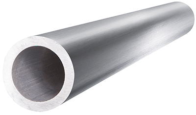
| Name: | Aluminum and Aluminum-Alloy Drawn Seamless Tubes B210-02 Alloy 5052 | ||||||||||
| Type Of Tubes | SMLS Pipe B210-02 Alloy 5052 | ||||||||||
|
Standard Specification for Aluminum and Aluminum-Alloy Drawn Seamless Tubes This standard is issued under the fixed designation B 210; the number immediately following the designation indicates the year of original adoption or, in the case of revision, the year of last revision. A number in parentheses indicates the year of last reapproval. A superscript epsilon (e) indicates an editorial change since the last revision or reapproval. This standard has been approved for use by agencies of the Department of Defense. |
|||||||||||
| Scope | |||||||||||
|
This specification covers aluminum and aluminum- alloy drawn seamless tubes in straight lengths and coils for general purpose and pressure applications in alloys (Note 2), tempers, and thicknesses shown. Coiled tubes are generally available only as round tubes with a wall thickness not exceeding 0.083 in. and only in nonheat-treatable alloys. Alloy and temper designations are in accordance with ANSI H35.1. The equivalent Unified Numbering System alloy designations are preceded by A9, for example, A91100 for aluminum designation 1100 in accordance with Practice E 527. NOTE 1—See Specification B 483 for aluminum-alloy drawn tubes for general purpose applications; Specification B 234 for aluminum-alloy drawn seamless tubes for condensers and heat exchangers; and Specifi-cation B241/B241M for aluminum-alloy seamless pipe and seamless extruded tube. NOTE 2—Throughout this specification, use of the term alloy in the general sense includes aluminum as well as aluminum alloy. A complete metric companion to Specification B 210 has been developed—Specification B 210M; therefore, no metric equivalents are presented in this specification. For acceptance criteria for inclusion of new aluminum and aluminum alloys in this specification, see Annex A2 |
|||||||||||
| Tensile Properties of Material as Supplied | |||||||||||
|
Limits—Tube shall conform to the tensile property requirements specified. Number of Specimens: For tubes having a nominal weight of less than 1 lb/linear ft, one tension test specimen shall be taken for each 1000 lb or fraction thereof in a lot. For tubes having a nominal weight of 1 lb or more/ linear ft, one tension test specimen shall be taken for each 1000 ft or fraction thereof in a lot. If the shipment contains tubes of more than one alloy, temper, or size, only those tubes of the same alloy, temper, and size shall be grouped for the purpose of selecting tension test specimens. Other procedures for selecting samples may be employed if agreed upon by the producer and the purchaser. Test Specimens—Geometry of test specimens and the location in the product from which they are taken shall be as specified in Test Methods B 557. Test Methods—The tension tests shall be made in accordance with Test Methods B 557. |
|||||||||||
| Tensile Property LimitsAB | |||||||||||
| Temper | Thickness,0 in. | Tensile Strength, ksi | Yield Strength0 (0.2 % offset), min, ksi | Elongation in 2 in or 4 x Diameter,E min, % | |||||||
| min | max | Full-Section Specimen | 0ut-Out Specimen | ||||||||
| Aluminum 1060F | |||||||||||
| O | 0.018-0.500 | 8.5 | 13.5 | 2.5 | |||||||
| H12 | 10.0 | 4.0 | |||||||||
| H14 | 12.0 | 10.0 | |||||||||
| H18 | 16.0 | 13.0 | |||||||||
| H113G | 8.5 | 2.5 | |||||||||
| Aluminum 1100F | |||||||||||
| O | 0.018-0.500 | 11.0 | 15.5 | 3.5 | |||||||
| H12 | 14.0 | 11.0 | |||||||||
| H14 | 16.0 | 14.0 | |||||||||
| H16 | 19.0 | 17.0 | |||||||||
| H18 | 22.0 | 20.0 | |||||||||
| H113G | 11.0 | 3.5 | |||||||||
| Alloy 2011 | |||||||||||
| T3 | 0.018-0.049 | 47.0 | 40.0 | ||||||||
| 0.050-0.500 | 47.0 | 40.0 | 10 | 8 | |||||||
| T4511 | 0.018-0.049 | 44.0 | 25.0 | ||||||||
| 20 | 18 | ||||||||||
| 0.050-0.259 | 44.0 | 25.0 | |||||||||
| 0.260-0.500 | 44.0 | 25.0 | 20 | 20 | |||||||
| Alloy 2014 | |||||||||||
| O | 0.018-0.500 | 32.0 | 16.0 max | ||||||||
| T4, T42H | 0.018-0.024 | 54.0 | 30.0 | 10 | |||||||
| 0.025-0.049 | 54.0 | 30.0 | 12 | 10 | |||||||
| 0.050-0.259 | 54.0 | 30.0 | 14 | 10 | |||||||
| 0.260-0.500 | 54.0 | 30.0 | 16 | 12 | |||||||
| T6, T62H | 0.018-0.024 | 65.0 | 55.0 | 7 | |||||||
| 0.025-0.049 | 65.0 | 55.0 | 7 | 6 | |||||||
| 0.050-0.259 | 65.0 | 55.0 | 8 | 7 | |||||||
| 0.260-0.500 | 65.0 | 55.0 | 9 | 8 | |||||||
| Alloy 2024 | |||||||||||
| O | 0.018-0.500 | 32.0 | 15.0 max | ||||||||
| T3H | 0.018-0.024 | 64.0 | 42.0 | 10 | |||||||
| 0.025-0.049 | 64.0 | 42.0 | 12 | 10 | |||||||
| 0.050-0.259 | 64.0 | 42.0 | 14 | 10 | |||||||
| 0.260-0.500 | 64.0 | 42.0 | 16 | 12 | |||||||
| T42H | 0.018-0.024 | 64.0 | 40.0 | 10 | |||||||
| 0.025-0.049 | 64.0 | 40.0 | 12 | 10 | |||||||
| 0.050-0.259 | 64.0 | 40.0 | 14 | 10 | |||||||
| 0.260-0.500 | 64.0 | 40.0 | 16 | 12 | |||||||
| Alloy 3003f | |||||||||||
| O | 0.010-0.024 | 14.0 | 19.0 | 5.0 | |||||||
| 0.025-0.049 | 14.0 | 19.0 | 5.0 | 30 | 20 | ||||||
| 0.050-0.259 | 14.0 | 19.0 | 5.0 | 35 | 25 | ||||||
| 0.260-0.500 | 14.0 | 19.0 | 5.0 | 30 | |||||||
| H12 | 0.010-0.500 | 17.0 | 12.0 | ||||||||
| H14 | 0.010-0.024 | 20.0 | 17.0 | 3 | |||||||
| 0.025-0.049 | 20.0 | 17.0 | 5 | 3 | |||||||
| 0.050-0.259 | 20.0 | 17.0 | 8 | 4 | |||||||
| 0.260-0.500 | 20.0 | 17.0 | |||||||||
| H16 | 0.010-0.024 | 24.0 | 21.0 | ||||||||
| 0.025-0.049 | 24.0 | 21.0 | 3 | 2 | |||||||
| 0.050-0.259 | 24.0 | 21.0 | 5 | 4 | |||||||
| 0.260-0.500 | 24.0 | 21.0 | |||||||||
| H18 | 0.010-0.024 | 27.0 | 24.0 | 2 | |||||||
| 0.025-0.049 | 27.0 | 24.0 | 3 | 2 | |||||||
| 0.050-0.259 | 27.0 | 24.0 | 5 | 3 | |||||||
| 0.260-0.500 | 27.0 | 24.0 | |||||||||
| H113g | 0.010-0.500 | 14.0 | 5.0 | ||||||||
| Alloy Alclad 3003 | |||||||||||
| O | 0.010-0.024 | 13.0 | 19.0 | 4.5 | |||||||
| 0.025-0.049 | 13.0 | 19.0 | 4.5 | 30 | 20 | ||||||
| 0.050-0.259 | 13.0 | 19.0 | 4.5 | 35 | 25 | ||||||
| 0.260-0.500 | 13.0 | 19.0 | 4.5 | 30 | |||||||
| H14 | 0.010-0.024 | 19.0 | 16.0 | ||||||||
| 0.025-0.049 | 19.0 | 16.0 | 5 | ||||||||
| 0.050-0.259 | 19.0 | 16.0 | 8 | 4 | |||||||
| 0.260-0.500 | 19.0 | 16.0 | |||||||||
| H18 | 0.010-0.500 | 26.0 | 23.0 | ||||||||
| H113g | 0.050-0.500 | 13.0 | 4.5 | ||||||||
| Alloy 3102f | |||||||||||
| O | 0.018-0.049 | 11.0 | 17.0 | 3.5 | 30' | 20' | |||||
| 0.050-0.065 | 11.0 | 17.0 | 3.5 | 35 | 25 | ||||||
| Alloy Alclad 3102f | |||||||||||
| O | 0.018-0.049 | 10.0 | 17.0 | 3.5 | 30' | 20' | |||||
| 25 | |||||||||||
| 0.050-0.065 | 10.0 | 17.0 | 3.5 | 35 | |||||||
| Alloy 3303f | |||||||||||
| O | 0.010-0.024 | 14.0 | 19.0 | 5.0 | |||||||
| 20 | |||||||||||
| 0.025-0.049 | 14.0 | 19.0 | 5.0 | 30 | |||||||
| 0.050-0.065 | 14.0 | 19.0 | 5.0 | 35 | 25 | ||||||
| Alloy Alclad 3303f | |||||||||||
| O | 0.010-0.024 | 13.0 | 19.0 | 4.5 | |||||||
| 0.025-0.049 | 13.0 | 19.0 | 4.5 | 30 | 20 | ||||||
| 0.050-0.065 | 13.0 | 19.0 | 4.5 | 35 | 25 | ||||||
| Alloy 5005f | |||||||||||
| Of | 0.018-0.500 | 15.0 | 21.0 | 5.0 | |||||||
| Alloy 5050f | |||||||||||
| Of | 0.018-0.500 | 18.0 | 24.0 | 6.0 | |||||||
| H32 | 22.0 | 16.0 | |||||||||
| H34 | 25.0 | 20.0 | |||||||||
| H36 | 27.0 | 22.0 | |||||||||
| H38 | 29.0 | 24.0 | |||||||||
| Alloy 5052f | |||||||||||
| Of | 0.018-0.450 | 25.0 | 35.0 | 10.0 | |||||||
| H32 | 31.0 | 23.0 | |||||||||
| H34 | 34.0 | 26.0 | |||||||||
| H36 | 37.0 | 29.0 | |||||||||
| H38 | 39.0 | 24.0 | |||||||||
| Alloy 5083f | |||||||||||
| OF | 0.018-0.450 | 39.0 | 51.0 | 16.0 | 14 | ||||||
| Alloy 5086f | |||||||||||
| OF | 0.018-0.450 | 35.0 | 46.0 | 14.0 | |||||||
| H32 | 40.0 | 28.0 | |||||||||
| H34 | 44.0 | 34.0 | |||||||||
| H36 | 47.0 | 38.0 | |||||||||
| Alloy 5154F | |||||||||||
| O | 0.010-0.450 | 30.0 | 41.0 | 11.0 | 10 | 10 | |||||
| H34 | 39.0 | 29.0 | 5 | 5 | |||||||
| H38 | 45.0 | 34.0 | |||||||||
| Alloy 5456f | |||||||||||
| O | 0.018 | 41.0 | 53.0 | 19.0 | 14 | ||||||
| Alloy 6061 | |||||||||||
| O | 0.018-0.500 | 22.0 | 14.0 max | 15 | 15 | ||||||
| T4 | 0.025-0.049 | 30.0 | 16.0 | 16 | 14 | ||||||
| 0.050-0.259 | |||||||||||
| 0.260-0.500 | 30.0 | 16.0 | 18 | 16 | |||||||
| 30.0 | 16.0 | 20 | 18 | ||||||||
| T42h | 0.025-0.049 | 30.0 | 14.0 | 16 | 14 | ||||||
| 0.050-0.259 | 30.0 | 14.0 | 18 | 16 | |||||||
| 0.260-0.500 | 30.0 | 14.0 | 20 | 18 | |||||||
| T6, T62H | 0.025-0.049 | 42.0 | 35.0 | 10 | 8 | ||||||
| 0.050-0.259 | 42.0 | 35.0 | 12 | 10 | |||||||
| 0.260-0.500 | 42.0 | 35.0 | 14 | 12 | |||||||
| Alloy 6063 | |||||||||||
| O | 0.018-0.500 | 19.0 | |||||||||
| T4, T42H | 0.025-0.049 | 22.0 | 10.0 | 16 | 14 | ||||||
| 0.050-0.259 | 22.0 | 10.0 | 18 | 16 | |||||||
| 0.260-0.500 | 22.0 | 10.0 | 20 | 18 | |||||||
| T6, T62H | 0.025-0.049 | 33.0 | 28.0 | 12 | 8 | ||||||
| 0.050-0.259 | 33.0 | 28.0 | 14 | 10 | |||||||
| 0.260-0.500 | 33.0 | 28.0 | 16 | 12 | |||||||
| T83 | 0.025-0.259 | 33.0 | 30.0 | 5 | |||||||
| T831 | 0.025-0.259 | 28.0 | 25.0 | 5 | |||||||
| T832 | 0.025-0.049 | 41.0 | 36.0 | 8 | 5 | ||||||
| 0.050-0.259 | 40.0 | 35.0 | 8 | 5 | |||||||
| Alloy 6262 | |||||||||||
| T6, T62H | 0.025-0.049 | 42.0 | 35.0 | 10 | 8 | ||||||
| 0.050-0.259 | 42.0 | 35.0 | 12 | 10 | |||||||
| 0.260-0.500 | 42.0 | 35.0 | 14 | 12 | |||||||
| T9 | 0.025-0.375 | 48.0 | 44.0 | 5 | 4 | ||||||
| Alloy 7075 | |||||||||||
| O | 0.025-0.049 | 40.0 | 21.0 max | 10 | 8 | ||||||
| 0.050-0.500 | 40.0 | 21.0 max | 12 | 10 | |||||||
| T6, T62H | 0.025-0.259 | 77.0 | 66.0 | 8 | 7 | ||||||
| 0.260-0.500 | 77.0 | 66.0 | 9 | 8 | |||||||
| T73J | 0.025-0.259 | 66.0 | 56.0 | 10 | 8 | ||||||
| 0.260-0.500 | 66.0 | 56.0 | 12 | 10 | |||||||
|
A See Annex A1. BTo determine conformance to this specification, each value for tensile strength and for yield strength shall be rounded to the nearest 0.1 ksi and each value for elongation to the nearest 0.5 % both in accordance with the rounding-off method of Practice E 29. CCoiled tube is generally available with a maximum wall thickness of 0.083 in. and only in nonheat-treatable alloys. D Yield strength to be determined only on straight tube. E Elongation of full-section and cut-out sheet-type specimens is measured in 2 in. of cut-out round specimens, in 4x specimen diameter. FIn this alloy tube other than round is produced only in the F (as drawn) and O tempers. Properties for F temper are not specified or guaranteed. G Beginning with the 1982 issue the requirements for the H112 tempers were replaced by the H113 temper, applicable to other than round tube, which is fabricated by cold-forming annealed round tube and acquires some temper in this forming operation. H Material in the T42 or T62 tempers is not available from the material producers. I For specified wall thickness under 0.025 in., elongation is not required. JMaterial in this temper exhibits improved resistance to stress corrosion compared to that of the T6 temper. The stress-corrosion resistance capability of individual lots is determined by testing the previously selected tension-test samples in accordance with the applicable electrical conductivity acceptance criteria |
|||||||||||
| Chemical Composition | |||||||||||
|
Limits—The tubes shall conform to the chemical com-position limits prescribed. Conformance shall be determined by the producer by analyzing samples taken at the time the ingots are poured, or samples taken from the finished or semi-finished product. If the producer has determined the chemical composition of the material during the course of manufacture, he shall not be required to sample and analyze the finished product. NOTE 3—It is standard practice in the United States aluminum industry to determine conformance to the chemical composition limits prior to further processing of ingots into wrought products. Due to the continuous nature of the process, it is not practical to keep a specific ingot analysis identified with a specific quantity of finished material. Number of Samples—The number of samples taken for determination of chemical composition shall be as follows: When samples are taken at the time the ingots are poured, at least one sample shall be taken for each group of ingots poured simultaneously from the same source of molten metal. When samples are taken from the finished or semi-finished product, a sample shall be taken to represent each 4000 lb or fraction thereof of material in the shipment, except that no more than one sample shall be required per piece. Methods of Sampling—Samples for determination of chemical composition shall be taken in accordance with one of the following methods: Samples for chemical analysis shall be taken from the material by drilling, sawing, milling, turning, or clipping a representative piece or pieces to obtain a prepared sample not less than 75 g. Sampling shall be in accordance with Practice E 55. Sampling for spectrochemical analysis shall be in accordance with Practices E 716. Samples for other methods of analysis shall be suitable for the form of material being analyzed and the type of analytical method used. NOTE 4—It is difficult to obtain a reliable analysis of each of the components of clad materials using material in its finished state. A reasonably accurate determination of the core composition can be made if the cladding is substantially removed prior to analysis. The cladding composition is more difficult to determine because of the relatively thin layer and because of diffusion of core elements to the cladding. The correctness of cladding alloy used can usually be verified by a combination of metallographic examination and spectrochemical analysis of the surface at several widely separated points. Methods of Analysis—The determination of chemical composition shall be made in accordance with suitable chemical (Test Methods E 34), or spectrochemical (Test Methods E 227, E 607, and E 1251), methods. Other methods may be used only when no published ASTM method is available. In case of dispute, the methods of analysis shall be agreed upon between the producer and the purchaser. |
|||||||||||
| Chemical Composition LimitsAB,C | |||||||||||
| Alloy | Silicon | Iron | Copper | Manganese | Magnesium | Chromium | Zinc | Titanium | Other ElementsD | Aluminum, min | |
| Each | TotalE | ||||||||||
| 5052 | 0.25 | 0.40 | 0.10 | 0.10 | 2.2-2.8 | 0.15-0.35 | 0.10 | 0.05 | 0.15 | remainder | |
|
ALimits are in weight percent maximum unless shown as a range or otherwise stated. BAnalysis shall be made for the elements for which limits are shown in this table. CFor purposes of determining conformance to these limits, an observed value or a calculated value obtained from analysis shall be rounded to the nearest unit in the last right-hand place of figures used in expressing the specified limit, in accordance with the rounding-off method of Practice E 29. D Others includes listed elements for which no specific limit is shown as well as unlisted metallic elements. The producer may analyze samples for trace elements not specified in the specification. However, such analysis is not required and may not cover all metallic Otherselements. Should any analysis by the producer or the purchaser establish that an Others element exceeds the limit of Each or that the aggregate of several Others elements exceeds the limit of Total, the material shall be considered non-conforming. E Other elements—Total shall be the sum of unspecified metallic elements 0.010 % or more, rounded to the second decimal before determining the sum. FVanadium 0.05 % max. G The aluminum content shall be calculated by subtracting from 100.00 % the sum of all metallic elements present in amounts of 0.010 % or more each, rounded to the second decimal before determining the sum. H Bismuth and lead each 0.20 – 0.6 %. I Alloy clad with Alloy 7072. J Bismuth and lead each 0.40-0.7 %. KComposition of cladding alloy as applied during the course of manufacture. The samples from finished tube shall not be required to conform to these limits. |
|||||||||||
| Lot Acceptance Criteria for Resistance to Stress-Corrosion | |||||||||||
| Alloy and Temper | Lot Acceptance Criteria | Lot Acceptance Status | |||||||||
| Electrical Conductivity,A,B % IACS | Level of Mechanical Properties | ||||||||||
| 7075-T73 | 40.0 or greater | per specified requirements | acceptable | ||||||||
| 38.0 through 39.9 | per specified requirements and yield strength does not exceed minimum by more than 11.9 ksi | acceptable | |||||||||
| 38.0 through 39.9 | per specified requirements but yield strength exceeds minimum by 12.0 ksi or more | unacceptableC | |||||||||
| less than 38.0 | any level | unacceptableC | |||||||||
| A The electrical conductivity shall be determined in accordance with Practice E 1004 in the following locations: | |||||||||||
| Wall Thickness, in. | Location | ||||||||||
| Up through 0.100 | surface of tensile sample | ||||||||||
| 0.101 and over | subsurface after removal of approximately 10 % of thickness. | ||||||||||
|
B For curved surfaces, the conductivity shall be measured on a machined flat spot; however, for small size tubes, a cut-out piece may be flattened and the conductiv¬ity determined. CWhen material is found to be unacceptable, it shall be reprocessed (additional precipitation heat treatment or resolution heat treatment and precipitation heat treat-ment). |
|||||||||||
| Materials and Manufacture | |||||||||||
|
The tube shall be produced by drawing an extruded tube made from hollow extrusion ingot (cast in hollow form or pierced) and extruded by the use of the die and mandrel method. The ends of coiled tube shall be crimped or otherwise sealed to avoid contamination during shipment. |
|||||||||||
| Flattening Properties | |||||||||||
|
Limits—When specified by the purchaser at the time of placing the order, round tube in alloys and tempers listed shall be tested in full section and withstand, without cracking, the minimum outside diameter flattening factor specified. Number of Specimens: For tubes having a nominal weight of less than 1 lb/linear ft, one flattening test specimen shall be taken for each 1000 lb or fraction thereof in a lot. For tubes having a nominal weight of 1 lb or more/ linear ft, one flattening test specimen shall be taken for each 1000 ft or fraction thereof in a lot. Methods of Test—Flattening test specimens shall be flattened sidewise under a gradually applied load so as to give a uniform radius of bend until the minimum outside diameter under load is not more than F times the wall thickness of the tube as specified. Alternative Bend Test—In case the tube does not flatten so as to give a uniform radius of bend, suitable jigs may be used to bring about this result, or a section of tube of not less than V2 in. in length, with the subtended arc not greater than one half nor less than one third of the circumference of the original tube, shall be removed from the material in question and without further treatment shall be bent around a mandrel having a diameter N times the wall thickness of the tube as specified. The bend shall be made with the pin placed on the inside surface of the specimen, with the longi-tudinal axis of the pin and the specimen parallel. The bend shall be continued until the specimen encloses at least 180° of the pin. After the flattening test, the outer surface of the tube shall be examined visually for cracks. Any evidence of cracking shall be cause for rejection. |
|||||||||||
| Minimum Outside Diameter Flattening Factor | |||||||||||
| Alloy | Temper | Wall Thickness, in. | Minimum Diameter Flattening Factor, F | ||||||||
| 5052 | O | 0.010-0.450 | 3 | ||||||||
| H32 | 0.010-0.450 | 6 | |||||||||
| H34 | 0.010-0.450 | 8 | |||||||||
| Minimum Bend Factor | |||||||||||
| 5052 | O | 0.010-0.249 | 1 | ||||||||
| H32 | 0.010-0.249 | 4 | |||||||||
| H34 | 0.010-0.249 | 6 | |||||||||
| Flaring Properties | |||||||||||
|
Limits—When specified by the purchaser at the time of placing the order, round tube in straight lengths in alloys and tempers 1100-H14, 3003-H14, 5052-O, and 6061-O with a nominal outside diameter of 0.375 in. or less, shall be capable of being double-flared to the configuration of Fig. 1, and with a nominal outside diameter over 0.375 in. shall be capable of being single-flared to the configuration of Fig. 2, without formation of cracks or other defects clearly visible to the unaided eye. Number of Specimens—When flare testing is specified in the order, for tube sizes having a nominal weight of less than 1 lb/linear ft, one flaring test specimen shall be taken for each verify conformance with Section 12 shall be as specified in 8.2. 1000 lb or fraction thereof in the lot. For tubes having a nominal weight of 1 lb or more/linear ft, one flaring test specimen shall be taken for each 1000 ft or fraction thereof in the lot. Preparation of Specimens—Specimens for flaring may be cut from any portion of the tube, or an entire tube may be used as a specimen. The end of the specimen to be flared shall be cut square, with the cut end smooth and free from burrs, but not rounded, except for sizes 0.375 in. and under. Test Methods—The specimen shall be forced axially with steady pressure over a hardened and polished tapered steel pine having a 74° included angle, to produce a flare having the permanent expanded outside diameter specified. |
|||||||||||
| FlareA, Dimensions, in. | |||||||||||
| Nominal OD | Expanded OD, min | Nominal OD | Expanded OD, min | ||||||||
| 0.125 | 0.224 | 0.750 | 0.937 | ||||||||
| 0.188 | 0.302 | 1.000 | 1.187 | ||||||||
| 0.250 | 0.359 | 1.250 | 1.500 | ||||||||
| 0.312 | 0.421 | 1.500 | 1.721 | ||||||||
| 0.375 | 0.484 | 1.750 | 2.106 | ||||||||
| 0.500 | 0.656 | 2.000 | 2.356 | ||||||||
| 0.625 | 0.781 | ||||||||||
| A Tube with intermediate nominal diameters shall meet the same requirements as those for the next largest diameter. Tube with nominal diameters larger than 2.000 or less than 0.125 in. shall meet requirements as agreed by the purchaser and producer. | |||||||||||
| Heat Treatment | |||||||||||
|
Unless specified in 11.2, producer or supplier heat treatment for the applicable tempers in shall be in accordance with AMS 2772. When specified, heat treatment of applicable tempers in Table 1 shall be in accordance with Practice B 918 |
|||||||||||
| Heat Treatment and Reheat Treatment Capability | |||||||||||
|
As-received material in the O or F temper and in Alloys 2014, 2024, 6061, and 6063 (within the size limitations specified and without the imposition of cold work) shall, after proper solution heat treatment and natural aging for not less than 4 days at room temperature, conform to the properties specified for T42 temper material. As received Alloy 7075 material in the O or F temper (within the size limitations specified and without the imposition of cold work) shall, after proper solution and precipitation heat treatment, conform to the properties specified for the T62 temper. Material in Alloys and Tempers 2014-T4, T6; 2024-T8; and 6063-T4, T6 shall, after proper resolution heat treatment and natural aging for not less than 4 days at room temperature, conform to the properties specified in for the T42 temper. NOTE 5—Beginning with the 1975 revision of B 210, 6061-T4 and T6 were deleted from this paragraph because experience has shown the reheat-treated material may develop large recrystallized grains and may fail to develop the tensile properties shown. Alloy 7075 material in T6 and T73 tempers shall, after proper resolution heat treatment and precipitation heat treat-ment, conform to the properties specified for the T62 temper. Material in T4 and T42 tempers shall, after proper precipitation heat treatment, conform to the properties specified in Table 1 for the T6 and T62 tempers, respectively. |
|||||||||||
| Stress-Corrosion Resistance | |||||||||||
|
For lot acceptance purposes, resistance to stress- corrosion cracking for each lot of 7075-T73 material shall be established by testing the previously selected tension-test samples to the criteria shown. The producer shall maintain records of all lots so tested and make them available for examination at the producer’s facility. |
|||||||||||
| Test for Leaks | |||||||||||
|
When specified by the purchaser at the time of placing the order, tube shall be tested for leaks by one of the following methods at the option of the producer. Method 1—Tubes 1V2 in. or less in diameter shall be tested pneumatically at not less than 60 psi air pressure while immersed in water or other suitable liquid. Any evidence of leakage shall be cause for rejection. Method 2—Tubes 1/2 in. or less in diameter shall be tested pneumatically at not less than 90 psi air pressure with a gage that will indicate loss of pressure. There shall not be any loss of pressure during a test period of at least 15-s duration. Method 3—Tubes shall be subjected to an eddy- current test in accordance with the procedures described in Practice E215. Reference standards or secondary standards having equivalent eddy-current response shall serve to define acceptance-rejection limits. These reference standards are ac-ceptable for testing any strain-hardened temper of the nonheat- treatable alloys and the F temper of heat-treatable alloys of Table 1 in tubes 1V2 in. or less in diameter having a maximum wall thickness of 0.083 in. For straight lengths of tube reference standards described in Appendixes X1 and X2 of Practice E 215 shall be used to standardize the equipment. Tubes 1V2 in. or less in diameter and maximum wall thickness of 0.083 in. that produce eddy-current indications less than those from the 2A holes of the applicable reference standard or an equivalent secondary standard shall be acceptable. Any tube having a discontinuity that produces an eddy-current indication equal to or greater than those from the 2A holes of the applicable reference standard or an equivalent secondary standard shall be rejected. For coiled tube secondary standards having an equivalent eddy-current response to a No. 70 (0.028 in.) and No. 60 (0.040 in.) drill holes shall be used to standardize the equipment. Tubes 3/16 to 1 in., incl, in diameter and maximum wall thickness of 0.083 in. that produce eddy-current indications less than those from the No. 60 hole of the secondary standard shall be acceptable. Any tube that produces an indication equal to or greater than those from the No. 60 hole of the secondary standard shall be rejected. Setup procedures shall include a check to ensure that tubes containing defects giving responses equal to or greater than that from a No. 60 hole are rejected at the speed of inspection. Tube in long coils may contain up to a specified number of defects per coil when agreed upon between the producer and purchaser. In cases where a specified number of defects per coil is allowed, the need for marking such defects in a coil shall be handled as agreed upon between the producer and purchaser. |
|||||||||||
| Special Requirements for Coiled Tubes | |||||||||||
| Expansion Test—Coiled tube in the annealed temper only shall be capable of being expanded on a hardened ground tapered steel pin having an included angle of 60°, to the following amounts, without signs of cracks, ruptures, or other defects clearly visible to the unaided eye: | |||||||||||
| Nominal Outside Diameter, in. | Expansion of Outside Diameter, % | ||||||||||
| Up through 0.750 | 40 | ||||||||||
| 0.751 and over | 30 | ||||||||||
|
NOTE 6—Other expansion capabilities may be required in special cases but shall be the subject of negotiation between the producer and the purchaser. Inside Cleanness Requirements and Test—When specified by the purchaser at the time of placing the order, the inside of coiled tube in the annealed temper only shall be sufficiently clean so that, when a test sample of 50 ft or a minimum of 375 in.2 internal surface is washed with 1,1,1-trichloroethane or trichloroethylene or equivalent, the residue remaining upon evaporation of the solvent shall not exceed 0.002 g/ft2 of interior surface. To perform the test a measured quantity of the solvent shall be pulled through the tube into a flask which is, in turn, attached to an aspirator or vacuum pump. The solvent shall then be transferred to a weighed container (crucible, evaporating dish, or beaker). The solvent in the container shall be evaporated to dryness on a low-temperature hot plate or steam bath. Overheating of the container shall be avoided to prevent charring of the residue. The container shall then be dried in an oven at 100 to 110°C for 10 min, cooled in a desiccator, and weighed. A blank determination shall be run on the measured quantity of solvent, and the gain in weight for the blank shall be subtracted from the weighings of the residue sample. The corrected weight shall then be calculated in grams of residue per internal area of tube. The quantity of the solvent used may vary with the size of tube being examined. A minimum quantity of 100 mL should be used for diameters up to V2 in. and should be increased proportionately for the larger sizes. The quantity of solvent used for the blank run shall be the same as that used for the actual examination of the tube sample. In performing the test, care must be exercised to clean the outside surface of the end of the sample to be immersed in the solvent. The sample must be prepared in such a manner as to prevent the inclusion in the residue of aluminum chips or dust resulting from the cutting of the sample. |
|||||||||||
| Cladding | |||||||||||
|
The aluminum-alloy cladding of Alloy Alclad 3003, Alloy Alclad 3102, and Alloy Alclad 3303 tubes shall comprise either the inside surface (only) or the outside surface (only) of the tube as specified. The purchaser shall specify whether “clad inside” or “clad outside” tubes are required. The Alloy Alclad 3003, Alloy Alclad 3102, and Alloy Alclad 3303 tubes shall be fabricated in such a manner that the cladding thickness will be approximately 10 % of the specified composite wall thickness for “clad inside” and 7 % for “clad outside.” When the thickness of the cladding is to be determined on finished tubes, transverse cross sections of at least three tubes from the lot shall be polished for examination with a metallurgical microscope. Using a magnification of 100X, the cladding thickness at four points, 90° apart, in each sample shall be measured and the average of the twelve measurements shall be taken as the thickness. In the case of tubes having a diameter larger than can properly be mounted for polishing and examination, the portions of the cross section polished for examination may consist of an arc about V2 in. in length. |
|||||||||||
| Dimensional Tolerances | |||||||||||
|
Variations from the specified or nominal dimensions shall not exceed the permissible variations prescribed in tables of ANSI H35.2. Sampling for Inspection—Examinations for dimen-sions shall be made to ensure conformance to the tolerances specified. |
|||||||||||
-
Aluminum and Aluminum-Alloy Drawn Seamless Tubes B210-02 Alloy 7075
-
Aluminum and Aluminum-Alloy Drawn Seamless Tubes B210-02 Alloy 6061
-
Aluminum and Aluminum-Alloy Drawn Seamless Tubes B210-02 Alloy 5086
-
Aluminum and Aluminum-Alloy Drawn Seamless Tubes B210-02 Alloy 2024
-
Aluminum and Aluminum-Alloy Drawn Seamless Tubes B210-02 Alloy 3003
-
Aluminum and Aluminum-Alloy Drawn Seamless Tubes B210-02 Alloy 1100

Mr. Thi
 Email:
theptangiabao@gmail.com
Email:
theptangiabao@gmail.com
|
 Skype:
|
 Hotline/ Zalo/ Wechat:
+84 982 384 688
Hotline/ Zalo/ Wechat:
+84 982 384 688
|

Ms. Hoa
|
Email:
theptangiabao@gmail.com
|
|
Skype:
|
|
Hotline/ Zalo/ Wechat:
+84 982 803 586
|

Ms. Phương
|
Email:
theptangiabao@gmail.com
|
|
Skype:
|
|
Hotline/ Zalo/ Wechat:
+84 971 567 341
|

Ms. Trinh
|
Email:
theptangiabao@gmail.com
|
|
Skype:
|
|
Hotline/ Zalo/ Wechat:
+84 971 567 943
|

Ms. Trân
|
Email:
theptangiabao@gmail.com
|
|
Skype:
|
|
Hotline/ Zalo/ Wechat:
+84 971 567 954
|
![]() HỒ CHÍ MINH CN1
HỒ CHÍ MINH CN1
Trụ Sở Hồ Chí Minh
Address : Số 8 đường số 20, P. Bình Hưng Hoà, Q. Bình Tân, TP. HCM
Phone : +84 982 384 688 - Email : theptangiabao@gmail.com
![]() HỒ CHÍ MINH CN2
HỒ CHÍ MINH CN2
Trụ Sở Hồ Chí Minh
Address : 27/9 đường Tân Thới Nhất 08, Phường Tân Thới Nhất, Q12, TP. HCM, VN
Phone : +84 982 384 688 - Email : theptangiabao@gmail.com
![]() BÀ RỊA - VŨNG TÀU
BÀ RỊA - VŨNG TÀU
Chi Nhánh Bà Rịa - Vũng Tàu
Address : 2597 Đ. Độc Lập, TT. Phú Mỹ, Tân Thành, Bà Rịa - Vũng Tàu, Việt Nam.
Phone : +84 974 618 834 - Email : chinhanhtangiabao@gmail.com
Social network


![]()
![]()


