-
 +84 982 384 688 - Mr. Thi | +84 982 803 586- Ms. Hoa
 -
 theptangiabao@gmail.com
 -
 Thứ 2 - Thứ 7 | 07:30 - 17:00
English

 Home
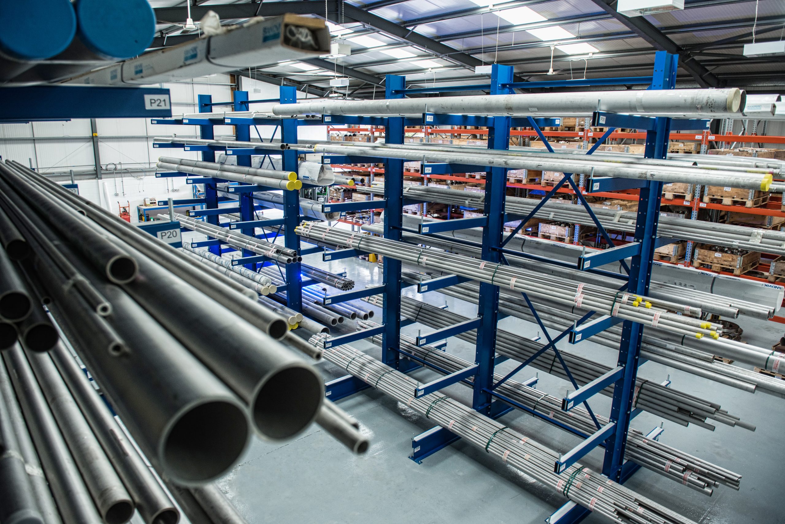
HomeWelded Tube, Stainless steel A249 Grade TP 310H

 Product info
| Supplier: | Tapgroup internation.,JSC |
| Address: | Số 32 Lô N4D, đường X2A, Yên Sở, Hoàng Mai, Hà Nội |
| Phone: | 0084 933 86 77 86 |
| Email: | info@tapgroup.vn |
| Website: | https://supplier-pipe-tube-ongthep.com |
| Insurance: | 12 tháng |
| Status: | Mới 100% |
| Origin: | China, Korea, Malaysia, Thailand, Japan, EU, G7 |
| Name: | Welded Tube, Stainless steel A249 Grade TP 310H | |||||||||||
|
Standard Specification for Welded Austenitic Steel Boiler, Superheater, Heat- Exchanger, and Condenser Tubes This standard is issued under the fixed designation A 249/A 249M; the number immediately following the designation indicates the year of original adoption or, in the case of revision, the year of last revision. A number in parentheses indicates the year of last reapproval. A superscript epsilon (e) indicates an editorial change since the last revision or reapproval. This standard has been approved for use by agencies of the Department of Defense. |
||||||||||||
| Scope | ||||||||||||
|
This specification covers nominal-wall-thickness welded tubes and heavily cold worked welded tubes made from the austenitic steels listed in Table 1, with various grades intended for such use as boiler, superheater, heat exchanger, or condenser tubes. Grades TP304H, TP309H, TP309HCb, TP310H, TP310HCb, TP316H, TP321H, TP347H, and TP348H are modifications of Grades TP304, TP309S, TP309Cb, TP310S, TP310Cb, TP316, TP321, TP347, and TP348, and are intended for high temperature service such as for superheaters and reheaters. The tubing sizes and thicknesses usually furnished to this specification are 1⁄8 in. [3.2 mm] in inside diameter to 12 in. [304.8 mm] in outside diameter and 0.015 to 0.320 in. [0.4 to 8.1 mm], inclusive, in wall thickness. Tubing having other dimensions may be furnished, provided such tubes comply with all other requirements of this specification. Mechanical property requirements do not apply to tubing smaller than 1⁄8 in. [3.2 mm] in inside diameter or 0.015 in. [0.4 mm] in thickness. Optional supplementary requirements are provided and, when one or more of these are desired, each shall be so stated in the order. The values stated in either inch-pound units or SI units are to be regarded separately as standard. Within the text, the SI units are shown in brackets. The values stated in each system are not exact equivalents; therefore, each system must be used independently of the other. Combining values from the two systems may result in nonconformance with the specification. The inch-pound units shall apply unless the “M” designation of this specification is specified in the order. The following safety hazards caveat pertains only to the test method described in the Supplementary Requirements of this specification. This standard does not purport to address all of the safety concerns, if any, associated with its use. It is the responsibility of the user of this standard to establish appropriate safety and health practices and determine the applicability of regulatory limitations prior to use. A specific warning statement is given in Supplementary Requirement S7, Note S7.1. |
||||||||||||
| Manufacture | ||||||||||||
|
The welded (WLD) tubes shall be made from flat-rolled steel by an automatic welding process with no addition of filler metal. Subsequent to welding and prior to final heat treatment, the tubes shall be cold worked either in both weld and base metal or in weld metal only. The method of cold working may be specified by the purchaser. When cold drawn, the purchaser may specify the minimum amount of reduction in cross-sectional area or wall thickness, or both. Heavily cold worked (HCW) tubes shall be made by applying cold working of not less than 35 % reduction in both wall and weld to a welded tube prior to the final anneal. No filler metal shall be used in the making of the weld. Prior to cold working, the weld shall be 100 % radiographically inspected in accordance with the requirements of ASME Boiler and Pressure Vessel Code, Section VIII, Division 1, latest revision, Paragraph UW 51. |
||||||||||||
| Chemical Requirements, %A | ||||||||||||
| Grade |
UNS DesignationB |
Carbon | Manganese | Phosphorous | Sulfur | Silicon | Chromium | Nickel | Molybdenum | NitrogenC | Copper | Other |
| TP 310H | S31009 | 0.04–0.10 | 2.00 | 0.045 | 0.030 | 1.00 | 24.0–26.0 | 19.0–22.0 | … | … | … | … |
|
A Maximum, unless otherwise indicated. B New designation established in accordance with Practice E 527 and SAE J1086. C The method of analysis for nitrogen shall be a matter of agreement between the purchaser and manufacturer. D For small diameter or thin walls, or both, where many drawing passes are required, a carbon maximum of 0.040 % is necessary in Grades TP 310HL and TP 316L. Small outside diameter tubes are defined as those less than 0.500 in. [12.7 mm] in outside diameter and light wall are those less than 0.049 in. [1.2 mm] in minimum wall thickness. |
||||||||||||
| Heat Treatment Requirements | ||||||||||||
| Grade | UNS Number | Solutioning Temperature, min or range | Quenching Method | |||||||||
| All grades not individually listed below | 1900 °F [1040 °C]A | B | ||||||||||
| … | S30815 | 1920 °F [1050 °C]B | B | |||||||||
| TP 310HCb | S30941 | 1900 °F [1040 °C]C B | B | |||||||||
| TP 310H | S31009 | 1900 °F [1040 °C] B | B | |||||||||
| TP 310HCb | S31041 | 1900 °F [1040 °C]C B | B | |||||||||
| … | S31254 | 2100 °F [1150 °C] B | B | |||||||||
| … | S31277 | 2050 °F [1120 °C] B | B | |||||||||
| TP 316H | S31609 | 1900 °F [1040 °C] B | B | |||||||||
| … | S31727 | 1975 °F [1080 °C]– B | B | |||||||||
| 2155 °F [1180 °C] B | B | |||||||||||
| … | S32053 | 1975 °F [1080 °C]– B | B | |||||||||
| TP 321 | S32100 |
2155 °F [1180 °C] B 1900 °F [1040 °C]C B |
B | |||||||||
| TP 321H | S32109 | 2000 °F [1100 °C]C B | B | |||||||||
| … | S32654 | 2100 °F [1150 °C] B | B | |||||||||
| … | S33228 | 2050 °F [1120 °C] B | B | |||||||||
| … | S34565 | 2050 °F [1120 °C]– B | B | |||||||||
| TP 347 | S34700 |
2140 °F [1170 °C] B 1900 °F [1040 °C]C B |
B | |||||||||
| TP 347H | S34709 | 2000 °F [1100 °C]C B | B | |||||||||
| TP 348 | S34800 | 1900 °F [1040 °C]C B | B | |||||||||
| TP 348H | S34809 | 2000 °F [1100 °C]C B | B | |||||||||
| … | S35045 | 2000 °F [1100 °C] D | D | |||||||||
| … | S38815 | 1950 °F [1065 °C] B | B | |||||||||
| … | N08367 | 2025 °F [1110 °C] B | B | |||||||||
| … | N08904 | 2000 °F [1100 °C] B | B | |||||||||
| … | N08926 | 2010 °F [1105 °C] B | B | |||||||||
|
AQuenched in water or rapidly cooled by other methods, at a rate sufficient to prevent reprecipitation of carbides, as demonstrated by the capability of passing Practices A 262, Practice E. The manufacturer is not required to run the test unless it is specified on the purchase order (See Supplementary Requirement S6). Note that Practices A 262 requires the test to be performed on sensitized specimens in the low carbon and stabilized types and on specimens representative of the as-shipped condition of the other types. In the case of low-carbon types containing 3 % or more molybdenum, the applicability of the sensitizing treatment prior to testing shall be a matter for negotiation between the seller and purchaser. BQuenched in water or rapidly cooled by other methods. CA solution treating temperature above 1950 °F [1065 °C] may impair resistance to intergranular corrosion after subsequent exposure to sensitizing conditions in the indicated grades. When specified by the purchaser, a lower temperature stabilization or re-solution anneal shall be used subsequent to the higher-temperature solution anneal prescribed in this table. DCooled in still air, or faster. |
||||||||||||
|
All material shall be furnished in the heat-treated condition in accordance with the requirements. A solution annealing temperature above 1950 °F [1065 °C] may impair the resistance to intergranular corrosion after subsequent exposure to sensitizing conditions in TP309HCb, TP310HCb, TP321, TP321H, TP347, TP347H, TP348, and TP348H. When specified by the purchaser, a lower temperature stabilization or re-solution anneal shall be used subsequent to the initial high temperature solution anneal. |
||||||||||||
| Number of Tubes in a Lot Heat Treated by the Continuous Process | ||||||||||||
| Size of Tube | Size of Lot | |||||||||||
|
2 in. [50.8 mm] and over in outside diameter and 0.200 in. [5.1 mm] and over in wall thickness |
not more than 50 tubes | |||||||||||
|
Less than 2 in. [50.8 mm] but over 1 in. [25.4 mm] in outside diameter or over 1 in. [25.4 mm] in outside diameter and under 0.200 in. [5.1 mm] in wall thickness |
not more than 75 tubes | |||||||||||
| 1 in. [25.4 mm] or less in outside diameter | not more than 125 tubes | |||||||||||
| Tensile and Hardness RequirementsA | ||||||||||||
| Grade |
UNS Designation |
Tensile Strength, min, ksi | Yield Strength, min, ksi | Elongation in 2 in. or 50 mm, | Rockwell Hardness Number, | |||||||
| TP 310H | S31009 | 75 [515] | 30 [205] | 35 | B90 | |||||||
|
A Not applicable to tubes less than 1⁄8 in. [3.2 mm] in outside diameter or having wall thickness below 0.015 in. [0.4 mm], or both. The tensile properties of such small diameter or thin wall tubes shall be a matter of agreement between the manufacturer and the purchaser. |
||||||||||||
| Reverse-Bend Test Requirement | ||||||||||||
|
A section 4 in. [100 mm] minimum in length shall be split longitudinally 90° on each side of the weld. The sample shall then be opened and bent around a mandrel with a maximum thickness of four times the wall thickness, with the mandrel parallel to the weld and against the original outside surface of the tube. The weld shall be at the point of maximum bend. There shall be no evidence of cracks, or of overlaps resulting from the reduction in thickness of the weld areas by cold working. When the geometry or size of the tubing make it difficult to test the sample as a single piece, the sample may be sectioned into smaller pieces provided a minimum of 4 in. of weld is subjected to reverse bending. NOTE 3—The reverse bend test is not applicable when the specified wall is 10 % or more of the specified outside diameter, or the wall thickness is 0.134 in. [3.4 mm] or greater, or the outside diameter size is less than 0.375 in. [9.5 mm]. Under these conditions the reverse flattening test of Specification A 1016/A 1016M shall apply. |
||||||||||||
| Grain Size Requirement | ||||||||||||
|
The grain size of Grades TP309H, TP309HCb, TP310H and TP310HCb, as determined in accordance with Test Methods E 112, shall be No. 6 or coarser. The grain size of Grades TP304H, TP316H, TP321H, TP347H and TP348H, as determined in accordance with Test Methods E 112, shall be No. 7 or coarser |
||||||||||||
|
Mechanical Tests and Grain Size Determinations Required |
||||||||||||
|
Tension Test—One tension test shall be made on a specimen for lots of not more than 50 tubes. Tension tests shall be made on specimens from two tubes for lots of more than 50 tubes. Flattening Test—One flattening test shall be made on specimens from each end of one finished tube, not the one used for the flange test, from each lot. Flange Test—One flange test shall be made on specimens from each end of one finished tube, not the one used for the flattening test, from each lot. Reverse-Bend Test—One reverse-bend test shall be made on a specimen from each 1500 ft [450 m] of finished tubing. Hardness Test—Brinell or Rockwell hardness tests shall be made on specimens from two tubes from each lot. Hydrostatic or Nondestructive Electric Test—Each tube shall be subjected to either the hydrostatic or the nondestructive electric test. The purchaser may specify which test is to be used. Grain Size—Grain size determinations on grades TP309H, TP309HCb, TP310H and TP310HCb shall be made on the same number of tubes as prescribed for the flattening test. Heavily cold worked tubes (HCW) shall be capable of passing the weld decay test listed in Supplementary S7 with a weld metal to base metal loss ratio of 0.90 to 1.10. The test is not required unless S7 is specified in the purchase order. |
||||||||||||
| Permissible Variations in Dimensions | ||||||||||||
|
Dimensional tolerances other than wall thickness tolerances shall be in accordance with Specification A 1016/ A 1016M. Wall thickness tolerances shall be 610 % of nominal wall for all tubing sizes. The wall thickness of the weld shall not exceed the wall thickness measured 90° from the weld by more than 6 % of the specified wall thickness or 0.004 in. [0.1 mm], whichever is greater. Requirements of 14.2 are not applicable when any of the following apply: When the specified wall thickness exceeds 12 % of the specified outside diameter; When the specified wall thickness exceeds 0.165 in. [4.2 mm]; When the specified OD exceeds 3 in. [76.2 mm]; or When the specified minimum yield strength given in Table 4 for the specified grade is 35 ksi [240 MPa] or greater. |
||||||||||||
| Workmanship, Finish, and Appearance | ||||||||||||
|
Finished tubes shall have smooth ends free of burrs and shall not deviate from straightness by more than 0.030 in. [0.8 mm] in 3 ft (900 mm] of length. |
||||||||||||
| Surface Condition | ||||||||||||
|
The tubes, after final heat treatment, shall be chemically descaled or pickled free of scale. When bright annealing is used, pickling or chemical descaling is not necessary. |
||||||||||||
| Forming Operations | ||||||||||||
| Tubes when inserted in the boiler shall stand expanding and beading without showing cracks or flaws. All tubes, when properly manipulated, shall be able to stand expanding and beading without showing cracks and flaws, and also shall stand all forging, welding, and bending operations necessary for application without developing defects. | ||||||||||||
| Stress-Relieved Annealed Tubes | ||||||||||||
|
For use in certain corrosives, particularly chlorides where stress corrosion may occur, tubes in Grades TP304L, TP316L, TP321, TP347, and TP348 may be specified in the stress-relieved annealed condition. Details of these supplemental requirements shall be agreed upon by the manufacturer and the purchaser. When stress-relieved tubes are specified, tubes shall be given a heat treatment at 1550 to 1650 °F [845 to 900 °C] after roll straightening. Cooling from this temperature range may be either in air or by slow cooling. No mechanical straightening is permitted after the stress-relief treatment. Straightness of the tubes shall be a matter of negotiation between the purchaser and manufacturer. |
||||||||||||
| Surface ConditionMinimum Wall Tubes | ||||||||||||
|
When specified by the purchaser, tubes shall be furnished on a minimum wall basis. Such tubes shall satisfy the minimum wall thickness requirements of Specification A 1016/A 1016M rather than the nominal wall requirements of this specification. In addition to the marking required by Section 18, the tubing shall be marked S2. |
||||||||||||
| Air Underwater Pressure Test | ||||||||||||
|
When specified, the tubing shall be examined by the air underwater pressure test. |
||||||||||||
| Stabilizing Heat Treatment | ||||||||||||
| Subsequent to the solution anneal required in Section 6, Grades TP309HCb, TP310HCb, TP321, TP321H, TP347, TP347H, TP348, and TP348H shall be given a stabilization heat treatment at a temperature lower than that used for the initial solution annealing heat treatment. The temperature of stabilization heat treatment shall be at a temperature as agreed upon between the purchaser and vendor. | ||||||||||||
| Unstraightened Tubes | ||||||||||||
|
When the purchaser specifies tubes unstraightened after final heat treatment (such as coils), the straightness requirement of Section 12 shall not apply and the minimum yield strength of Table 3 shall be reduced by 5 ksi [35 MPa]. S5.2 On the certification, and wherever the grade designation for unstraightened tubing appears, it shall be identified with the suffix letter “U” (for example, 304-U, 321-U, etc.). |
||||||||||||
| Intergranular Corrosion Test | ||||||||||||
|
When specified, material shall pass intergranular corrosion tests conducted by the manufacturer in accordance with Practices A 262, Practice E. NOTE S6.1—Practice E requires testing on the sensitized condition for low carbon or stabilized grades, and on the as-shipped condition for other grades. A stabilization heat treatment in accordance with Supplementary Requirement S4 may be necessary and is permitted in order to meet this requirement for the grades containing titanium or columbium, particularly in their H versions. |
||||||||||||
| Weld Decay Test | ||||||||||||
|
This test is not applicable to alloys with a nickel content $ 19.0 % or a molybdenum content $ 4.00 %, or both. When specified by the purchase order, one sample from each lot of tubing shall be subjected to testing in a boiling mixture of 50 % reagent grade hydrochloric acid and 50 % water. Approximately 2-in. long samples shall be prepared from a production length of tubing. Shorter, 1-in. samples may be used for small diameter (1/2-in. and below) tubing. Split the sample longitudinally to allow for easy micrometer measurements. The sample may be one piece which contains the weld and at least 90° of base-metal to one side of the weld. Alternately, the sample may be two separate pieces with one containing the weld and a similar size section from the balance of the tube opposite the weld consisting of 100 % base metal. Remove all burrs and sharp edges by lightly grinding. Remove dust and grease by cleaning with soap and water or other suitable solvents. Then, place sample(s) in the flask. It is not recommended to test more than four samples together, or to mix alloy types. Prepare the hydrochloric acid solution by slowly adding reagent grade (approximately 37 %) hydrochloric acid to an equal volume of distilled water. (Warning—Protect eyes and use rubber gloves when handling acid. Mixing shall be done under a hood and testing shall be run under a hood.) The test container shall be a 1-L Erlenmeyer flask equipped with ground-glass joints and an Ahlin condenser. The volume of the solution shall be approximately 700 mL. Measure the thickness of the tube at five locations along the weld area and at five locations along the base-metal section. In both cases, take measurements at approximately equal longitudinal intervals along the section lengths. Make these measurements with a sharp pointed micrometer accurate to at least 0.001 in. The micrometer must be suitable for measuring the small features in the surface after testing. Typical pin micrometers have tapered anvils with a tip radius of less than 0.015 in. Immerse the samples into the solution. Add boiling chips and bring to a boil. Allow the chips to remain boiling throughout the test. The time of testing shall be that which is required to remove 40 to 60 % of the original base-metal thickness (usually 2 h or less). If more than 60 % of the base-metal thickness remains, the sample may be removed after 24 h. At the end of the test period, remove the samples from the solution, rinse with distilled water, and dry. After exposure to the test solution, repeat the tubethickness measurement as in S7.6. If the thinning is not uniform across the width of the weld, then two sets of weld-metal measurement are required. One set of measurements is to be taken along the centerline of the weld. The second set of measurements is to be taken in the thinnest area of the weld. Calculate the corrosion ratio, R, for both sections of the weld as follows in Eq1: where: Wo = average weld-metal thickness before the test, W = average weld-metal thickness after the test, Bo = average base-metal thickness before the test, and B = average base-metal thickness after the test. A corrosion ratio of 1.25 or less for the thinnest section of the weld is permissible. Other criteria, such as a ratio of 1.00 or less, may be specified upon agreement between the producer and the purchaser. |
||||||||||||
| Special Applications | ||||||||||||
| For special applications, such as hydraulic expansion of tubes into tube sheets, there shall be no dimensional indication of the weld. Tubes ordered to this requirement shall bear the additional marking of NB. | ||||||||||||
| Additional Testing of Welded Tubing per ASME Request | ||||||||||||
|
Each tube shall be subjected to an ultrasonic inspection employing Practices E 273 or E 213 with the rejection criteria referenced in Specification A 1016/A 1016M. If Practice E 273 is employed, a 100 % volumetric inspection of the entire length of each tube shall also be performed using one of the nondestructive electric tests permitted by Specification A 1016/A 1016M. The test methods described in the supplement may not be capable of inspecting the end portions of tubes. This condition is referred to as end effect. This portion, as determined by the manufacturer, shall be removed and discarded. In addition to the marking prescribed in Specification A 1016/A 1016M, “S9” shall be added after the grade designation. |
||||||||||||
-
Welded Tube, Stainless steel A249 Grade TP XM-15
-
Welded Tube, Stainless steel A249 Grade TP 348H
-
Welded Tube, Stainless steel A249 Grade TP 348
-
Welded Tube, Stainless steel A249 Grade TP 347H
-
Welded Tube, Stainless steel A249 Grade TP 347
-
Welded Tube, Stainless steel A249 Grade TP 321H
-
Welded Tube, Stainless steel A249 Grade TP 321
-
Welded Tube, Stainless steel A249 Grade TP 317L
-
Welded Tube, Stainless steel A249 Grade TP 317
-
Welded Tube, Stainless steel A249 Grade TP 316LN
-
Welded Tube, Stainless steel A249 Grade TP 316N
-
Welded Tube, Stainless steel A249 Grade TP 316H
-
Welded Tube, Stainless steel A249 Grade TP 316L
-
Welded Tube, Stainless steel A249 Grade TP 316
-
Welded Tube, Stainless steel A249 Grade TP 310HCb
-
Welded Tube, Stainless steel A249 Grade TP 310Cb
-
Welded Tube, Stainless steel A249 Grade TP 310S
-
Welded Tube, Stainless steel A249 Grade TP 309HCb
-
Welded Tube, Stainless steel A249 Grade TP 309Cb
-
Welded Tube, Stainless steel A249 Grade TP 309H
-
Welded Tube, Stainless steel A249 Grade TP 309S
-
Welded Tube, Stainless steel A249 Grade TP 305
-
Welded Tube, Stainless steel A249 Grade TP 304LN
-
Welded Tube, Stainless steel A249 Grade TP 304N
-
Welded Tube, Stainless steel A249 Grade TP 304H
-
Welded Tube, Stainless steel A249 Grade TP 304L
-
Welded Tube, Stainless steel A249 Grade TP 304
-
Welded Tube, Stainless steel A249 Grade TP XM-29
-
Welded Tube, Stainless steel A249 Grade TP XM-19
-
Welded Tube, Stainless steel A249 Grade TP 202

Mr. Thi
 Email:
theptangiabao@gmail.com
Email:
theptangiabao@gmail.com
|
 Skype:
|
 Hotline/ Zalo/ Wechat:
+84 982 384 688
Hotline/ Zalo/ Wechat:
+84 982 384 688
|

Ms. Hoa
|
Email:
theptangiabao@gmail.com
|
|
Skype:
|
|
Hotline/ Zalo/ Wechat:
+84 982 803 586
|

Ms. Phương
|
Email:
theptangiabao@gmail.com
|
|
Skype:
|
|
Hotline/ Zalo/ Wechat:
+84 971 567 341
|

Ms. Trinh
|
Email:
theptangiabao@gmail.com
|
|
Skype:
|
|
Hotline/ Zalo/ Wechat:
+84 971 567 943
|

Ms. Trân
|
Email:
theptangiabao@gmail.com
|
|
Skype:
|
|
Hotline/ Zalo/ Wechat:
+84 971 567 954
|
![]() HỒ CHÍ MINH CN1
HỒ CHÍ MINH CN1
Trụ Sở Hồ Chí Minh
Address : Số 8 đường số 20, P. Bình Hưng Hoà, Q. Bình Tân, TP. HCM
Phone : +84 982 384 688 - Email : theptangiabao@gmail.com
![]() HỒ CHÍ MINH CN2
HỒ CHÍ MINH CN2
Trụ Sở Hồ Chí Minh
Address : 27/9 đường Tân Thới Nhất 08, Phường Tân Thới Nhất, Q12, TP. HCM, VN
Phone : +84 982 384 688 - Email : theptangiabao@gmail.com
![]() BÀ RỊA - VŨNG TÀU
BÀ RỊA - VŨNG TÀU
Chi Nhánh Bà Rịa - Vũng Tàu
Address : 2597 Đ. Độc Lập, TT. Phú Mỹ, Tân Thành, Bà Rịa - Vũng Tàu, Việt Nam.
Phone : +84 974 618 834 - Email : chinhanhtangiabao@gmail.com
Social network


![]()
![]()


