-
 +84 982 384 688 - Mr. Thi | +84 982 803 586- Ms. Hoa
 -
 theptangiabao@gmail.com
 -
 Thứ 2 - Thứ 7 | 07:30 - 17:00
English

 Home
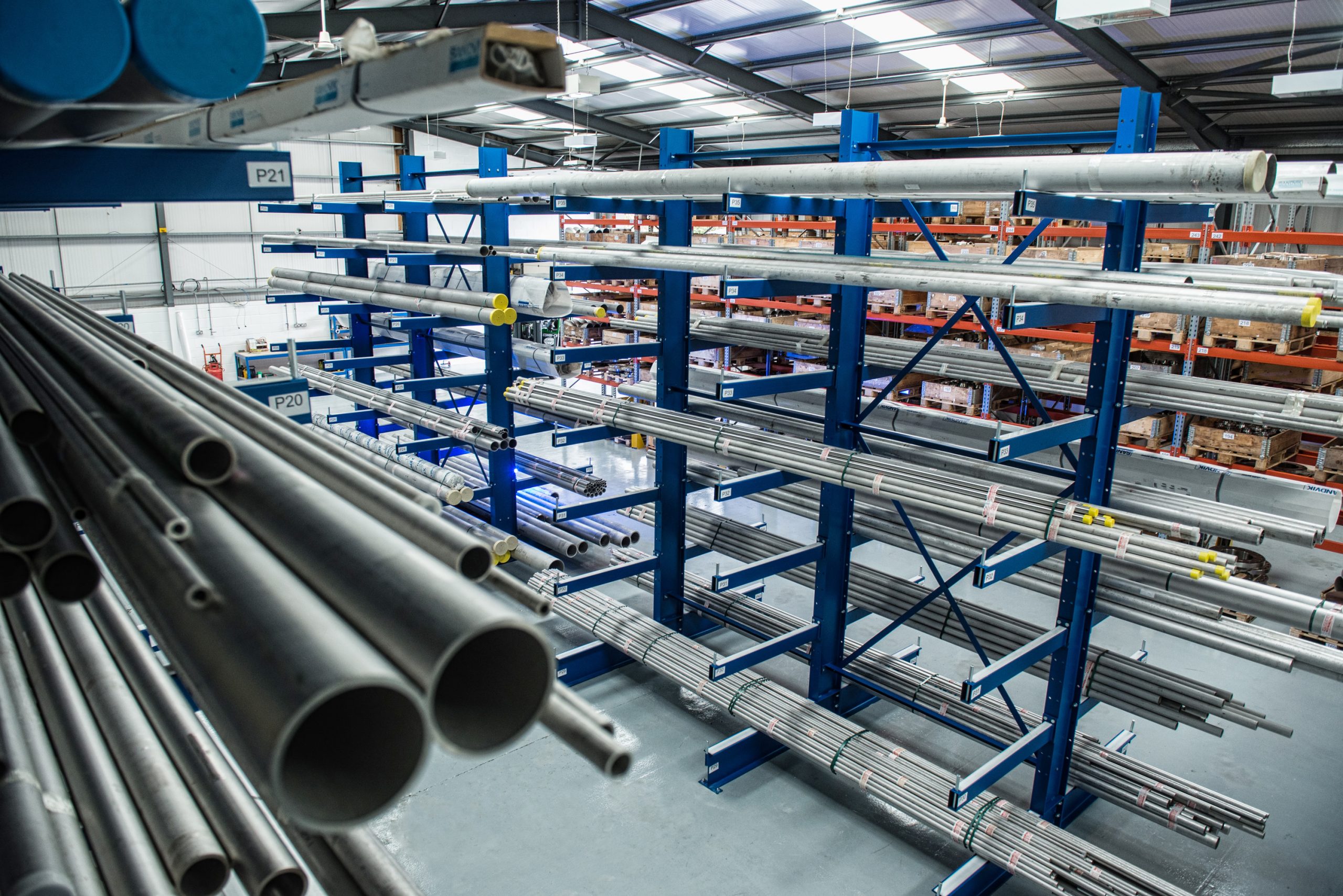
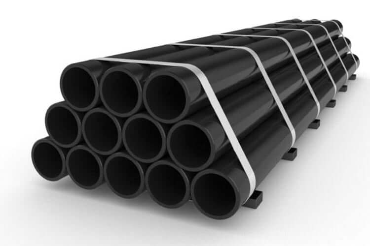
HomeSeamless and Welded Steel Pipe Low Temperature A333 Grade 3
 Product info
| Supplier: | Tapgroup internation.,JSC |
| Address: | Số 32 Lô N4D, đường X2A, Yên Sở, Hoàng Mai, Hà Nội |
| Phone: | 0084 933 86 77 86 |
| Email: | info@tapgroup.vn |
| Website: | https://supplier-pipe-tube-ongthep.com |
| Insurance: | 12 tháng |
| Status: | Mới 100% |
| Origin: | China, Korea, Malaysia, Thailand, Japan, EU, G7 |
| Name: | Seamless and Welded Steel Pipe Low Temperature A333 Grade 3 | |||||||||||||||||||
| Standard Specification for Seamless and Welded Steel Pipe for Low-Temperature Service A333 Grade 3 | ||||||||||||||||||||
| Type of Pipe | Seamless Pipe A333 Grade 3 | Pipe A333 Grade 3, SMLS | ||||||||||||||||||
| Welded Pipe A333 Grade 3 | Pipe A333 Grade 3, ERW | |||||||||||||||||||
| Chemical Requirements | ||||||||||||||||||||
| Element | Compositions, % | |||||||||||||||||||
| Grade 1A | Grade 3 | Grade 4 | Grade 6a | Grade 7 | Grade 8 | Grade 9 | Grade 10 | Grade 11 | ||||||||||||
| Cacbon max | 0.3 | 0.19 | 0.12 | 0.3 | 0.19 | 0.13 | 0.2 | 0.2 | 0.1 | |||||||||||
| Manganese | 0.40-1.06 | 0.31-0.64 | 0.50-1.05 | 0.29-1.06 | 0.90 max | 0.90 max | 0.40-1.06 | 1.15-1.50 | 0.60 max | |||||||||||
| Phosphorus, max | 0.025 | 0.025 | 0.025 | 0.025 | 0.025 | 0.025 | 0.025 | 0.035 | 0.025 | |||||||||||
| Sulfur, max | 0.025 | 0.025 | 0.025 | 0.025 | 0.025 | 0.025 | 0.025 | 0.015 | 0.025 | |||||||||||
| Silicon | … | 0.18-0.37 | 0.08-0.37 | 0.10 min | 0.13-0.32 | 0.13-0.32 | … | 0.10-0.35 | 0.35 max | |||||||||||
| Nickel | … | 3.18-3.82 | 0.47-0.98 | … | 2.03-2.57 | 8.40-9.60 | 1.60-2.24 | 0.25 max | 35.0-37.0 | |||||||||||
| Chromium | … | … | 0.44-1.01 | … | … | … | … | 0.15 max | 0.50 max | |||||||||||
| Copper | … | … | 0.40-0.75 | … | … | … | 0.75-1.25 | 0.15 max | … | |||||||||||
| Aluminum | … | … | 0.04-0.30 | … | … | … | … | 0.06 max | … | |||||||||||
| Vanadium max | … | … | … | … | … | … | … | 0.12 | … | |||||||||||
| Columbium max | … | … | … | … | … | … | … | 0.05 | … | |||||||||||
| Molybdenum max | … | … | … | … | … | … | … | 0.05 | 0.50 max | |||||||||||
| Cobalt | … | … | … | … | … | … | … | … | 0.50 max | |||||||||||
| AFor each reduction of 0.01% carbon below 0.30%, an increase of 0.05% manganese above 1.06% would be permitted to a maximum of 1.35% manganese. | ||||||||||||||||||||
| Stress relieving of test pieces | ||||||||||||||||||||
| Metal temperatureA,B |
Minimum holding time, h/in. [min/mm] of thickness |
|||||||||||||||||||
| Grade 1, 3, 6, 7, and 10 | Grade 4C | |||||||||||||||||||
| °F | °C | °F | °C | |||||||||||||||||
| 1100 | 600 | 1150 | 620 | 1 [2.4] | ||||||||||||||||
| 1050 | 565 | 1100 | 600 | 2 [4.7] | ||||||||||||||||
| 1000 | 540 | 1050 | 565 | 3 [7.1] | ||||||||||||||||
| AFor intermediate temperatures, the holding time shall be determined by straight line interpolation. | ||||||||||||||||||||
| BGrade 8 shall be stress relieved at 1025 to 1085°F, [550 to 585°C], held for minimum time of 2 h for thickness up to 1.0 in. [25.4mm], plus a minimum of 1 h for each additional inch [25.4mm] of thickness and cooled at a minimim rate of 300°F [165°C}/h in air or water to a temperature not exceeding 600°F [315°C]. | ||||||||||||||||||||
| CUnless otherwise specified, Grade 4 shall be stress relieved at 1150°F [620°C]. | ||||||||||||||||||||
| Tensile requirements | ||||||||||||||||||||
| Grade 1 | Grade 3 | Grade 4 | Grade 6a | Grade 7 | Grade 8 | Grade 9 | Grade 10 | Grade 11 | ||||||||||||
| psi | Mpa | psi | Mpa | psi | Mpa | psi | Mpa | psi | Mpa | psi | Mpa | psi | Mpa | psi | Mpa | psi | Mpa | |||
| Tensile strength, min | 55 000 | 380 | 65 000 | 450 | 60 000 | 415 | 60 000 | 415 | 65 000 | 450 | 100 000 | 690 | 63 000 | 435 | 80 000 | 550 | 65 000 | 450 | ||
| Yield strength, min | 30 000 | 205 | 35 000 | 240 | 35 000 | 240 | 35 000 | 240 | 35 000 | 240 | 75 000 | 515 | 46 000 | 315 | 65 000 | 450 | 35 000 | 240 | ||
| Longitudinal | Transverse | Longitudinal | Transverse | Longitudinal | Transverse | Longitudinal | Transverse | Longitudinal | Transverse | Longitudinal | Transverse | Longitudinal | Transverse | Longitudinal | Transverse | Longitudinal | ||||
| Elongation in 2 in. or 50 mm, or 4D, min, %: Basic minimum elongation for walls 5/16 in. [8mm] and over in thickness, strip tests, and for all small sizes tested in full section | 35 | 25 | 30 | 20 | 30 | 16.5 | 30 | 16.5 | 30 | 22 | 22 | … | 28 | … | 22 | … | 18A | |||
| When standard round 2-in. or 50-mm gage length or proportionally smaller size test specimen with the gage length equal to 4D (4 times the diameter) is used | 28 | 20 | 22 | 14 | 22 | 12 | 22 | 12 | 22 | 14 | 16 | … | … | … | 16 | … | … | |||
| For strip tests, a deduction for each 1/32 in. [0.8mm] decrease in wall thickness below 5/16 in. [8mm] from the basic minimum elongation of the following percentage. | 1.75B | 1.25B | 1.50B | 1.00B | 1.50B | 1.00B | 1.5B | 1.00B | 1.5B | 1.00B | 1.25B | … | 1.50B | … | 1.25B | … | … | |||
| Wall thickness | Elongation in 2 in. Or 50 mm, min, %C | |||||||||||||||||||
| Grade 1 | Grade 3 | Grade 4 | Grade 6 | Grade 7 | Grade 8 | Grade 9 | Grade 10 | |||||||||||||
| in. | mm | Longitudinal | Transverse | Longitudinal | Transverse | Longitudinal | Transverse | Longitudinal | Transverse | Longitudinal | Transverse | Longitudinal | Transverse | Longitudinal | Transverse | Longitudinal | Transverse | |||
| 5/16 90.312) | 8 | 35 | 25 | 30 | 20 | 30 | 16 | 30 | 16 | 30 | 22 | 22 | … | 28 | … | 22 | … | |||
| 9/32 (0.281) | 7.2 | 33 | 24 | 28 | 19 | 28 | 15 | 28 | 15 | 28 | 21 | 21 | … | 26 | … | 21 | … | |||
| 1/4 (0.250 ) | 6.4 | 32 | 23 | 27 | 18 | 27 | 15 | 27 | 15 | 27 | 20 | 20 | … | 25 | … | 20 | … | |||
| 7/32 (0.219) | 5.6 | 30 | … | 26 | … | 26 | … | 26 | … | 26 | … | 18 | … | 24 | … | 18 | … | |||
| 3/16 (0.188) | 4.8 | 28 | … | 24 | … | 24 | … | 24 | … | 24 | … | 17 | … | 22 | … | 17 | … | |||
| 5/32 (0.156) | 4 | 26 | … | 22 | … | 22 | … | 22 | … | 22 | … | 16 | … | 20 | … | 16 | … | |||
| 1/8 (0.125) | 3.2 | 25 | … | 21 | … | 21 | … | 21 | … | 21 | … | 15 | … | 19 | … | 15 | … | |||
| 3/32 (0.094) | 2.4 | 23 | … | 20 | … | 20 | … | 20 | … | 20 | … | 13 | … | 18 | … | 13 | … | |||
| 1/16 (0.062) | 1.6 | 21 | … | 18 | … | 18 | … | 18 | … | 18 | … | 12 | … | 16 | … | 12 | … | |||
| AElongation of grade 11 is for all walls and small sizes tested in full section. | ||||||||||||||||||||
| BThe following table gives the calculated minimum values. | ||||||||||||||||||||
| CCaculated elongation requirements shall be rounded to the nearest whole number. | ||||||||||||||||||||
| Note-the preceding table gives the computed minimum elongation values for each 1/32-in.[0.80-mm] decrease in wall thickness. Where the wall thickness lies between two values shown above, the minimum elongation value is determined by the following equation: | ||||||||||||||||||||
| Grade | Direction of test | Equation | ||||||||||||||||||
| 1 | Longitudinal | E = 56t +17.50 [E =2.19t + 17.50] | ||||||||||||||||||
| Transverse | E = 40t + 12.50 [E = 1.56t + 12.50] | |||||||||||||||||||
| 3 | Longitudinal | E = 48t + 15.00 [ E = 1.87t + 15.00] | ||||||||||||||||||
| Transverse | E = 32t + 10.00 [ E = 1.25t + 10.00] | |||||||||||||||||||
| 4 | Longitudinal | E = 48t + 15.00 [E = 1.87t + 15.00] | ||||||||||||||||||
| Transverse | E = 32t + 6.50 [E = 1.25t+ 6.50] | |||||||||||||||||||
| 6 | Longitudinal | E = 48t + 15.00 [E = 1.87t + 15.00] | ||||||||||||||||||
| Transverse | E = 32t + 6.50 [E = 1.25t + 6.50] | |||||||||||||||||||
| 7 | Longitudinal | E = 48t + 15.00 [E = 1.87t + 15.00] | ||||||||||||||||||
| Transverse | E = 32t + 11.00 [E = 1.25t + 11.00] | |||||||||||||||||||
| 8 and 10 | Longitudinal | E = 40t + 9.50 [E = 1.56t + 9.50] | ||||||||||||||||||
| 9 | Longitudinal | E = 48t + 13.00 [E = 1.87t + 13.00] | ||||||||||||||||||
| Where: | ||||||||||||||||||||
| E = elongation in 2 in. or 50 mm, in %, and | ||||||||||||||||||||
| t = actual thickness of specimen, in. [mm]. | ||||||||||||||||||||
| Impact requirement for grades 1,3,4,6,7,9, and 10 | ||||||||||||||||||||
| Size of specimen, mm | Minimum average notched bar impact value of each set of three specimensA | Minimum notched bar impact value of one specimen only of a setA | ||||||||||||||||||
| ft lbf | J | ft lbf | J | |||||||||||||||||
| 10 by 10 | 13 | 18 | 10 | 14 | ||||||||||||||||
| 10 by 7.5 | 10 | 14 | 8 | 11 | ||||||||||||||||
| 10 by 6.67 | 9 | 12 | 7 | 9 | ||||||||||||||||
| 10 by 5 | 7 | 9 | 5 | 7 | ||||||||||||||||
| 10 by 3.33 | 5 | 7 | 3 | 4 | ||||||||||||||||
| 10 by 2.5 | 4 | 5 | 3 | 4 | ||||||||||||||||
| AStraight line interpolation for intermediate values is permitted. | ||||||||||||||||||||
| Impact temperature reduction | ||||||||||||||||||||
| Specimen width along notch or actual material thickness | Temperature reduction, degrees colderA | |||||||||||||||||||
| in. | mm | °F | °C | |||||||||||||||||
| 0.394 | 10 (standard size) | 0 | 0 | |||||||||||||||||
| 0.354 | 9 | 0 | 0 | |||||||||||||||||
| 0.315 | 8 | 0 | 0 | |||||||||||||||||
| 0.295 | 7.5 (3/4 std. size) | 5 | 3 | |||||||||||||||||
| 0.276 | 7 | 8 | 4 | |||||||||||||||||
| 0.262 | 6.67 (2/3 std. size) | 10 | 5 | |||||||||||||||||
| 0.236 | 6 | 15 | 8 | |||||||||||||||||
| 0.197 | 5 (1/2 std. size) | 20 | 11 | |||||||||||||||||
| 0.158 | 4 | 30 | 17 | |||||||||||||||||
| 0.131 | 3.33 (1/3 std. size) | 35 | 19 | |||||||||||||||||
| 0.118 | 3 | 40 | 22 | |||||||||||||||||
| 0.099 | 2.5 (1/4 std. size) | 50 | 28 | |||||||||||||||||
| AStraight line interpolation for intermediate values is permitted | ||||||||||||||||||||
| Grade | Minimum impact test temperature | |||||||||||||||||||
| °F | °C | |||||||||||||||||||
| 1 | -50 | -45 | ||||||||||||||||||
| 3 | -150 | -100 | ||||||||||||||||||
| 4 | -150 | -100 | ||||||||||||||||||
| 6 | -50 | -45 | ||||||||||||||||||
| 7 | -100 | -75 | ||||||||||||||||||
| 8 | -320 | -195 | ||||||||||||||||||
| 9 | -100 | -75 | ||||||||||||||||||
| 10 | -75 | -60 | ||||||||||||||||||
| Wall Thickness: Welded and Seamless Wrought Steel Pipe, ANSI /ASME B36.10M | ||||||||||||||||||||
| Schedule (SCH) | SCH 5 | SCH 10 | SCH 20 | SCH 30 | SCH STD | SCH 40 | SCH 60 | SCH XXS | SCH 80 | SCH 100 | SCH 120 | SCH 160 | SCH XXS | SCH XX.H | ||||||
| End of pipe end | ||||||||||||||||||||
| Plain Ends (PE) | The PE pipes will generally be used for the smaller diameters pipe systems and in combination with Slip On flanges and Socket Weld fittings and flanges. | |||||||||||||||||||
| Threaded Ends (TE) | The TE implementation speaks for itself, this performance will generally used for small diameters pipe systems, and the connections will be made with threaded flanges and threaded fittings. | |||||||||||||||||||
| Beveled Ends (BE) | The BE implementation is applied to all diameters of buttweld flanges or buttweld fittings, and will be directly welded (with a small gap 3-4 mm) to each other or to the pipe. Ends are mostly be beveled to angle 30° (+ 5° / -0°) with a root face of 1.6 mm (± 0.8 mm). | |||||||||||||||||||
| Grooved ends | (example Victaulic pipes): these are pipes that allow a quick connection, used for non-critical applications | |||||||||||||||||||
| Threaded and coupled ends |
(T&C), generally used for gas distribution, Threaded connections are the most common pipe fittings used in oil and gas transportation systems. Due to external vibrations, cyclic loads, and pollution, the fitting parts may start getting loose, which could result in pipeline leaks and other environmental disasters. It is of great significance to develop a reliable technique that could provide… |
|||||||||||||||||||
| Type end : Plain Ends / Beveled Ends: Pipe | ||||||||||||||||||||
|
• Bevel End (BE) • Bevel Both Ends (BBE) • Bevel Large End (BLE) • Bevel One End (BOE) • Bevel Small End (BSE) • Bevel for Welding (BFW) • Buttweld End (BE) |
• End of Pipe (EOP) • Flange One End (FOE) • Plain End (PE) • Plain Both Ends (PBE) • Plain One End (POE) • Thread End (TE) • Thread Both Ends (TBE) |
• Thread Large End (TLE) • Thread One End (TOE) • Thread Small End (TSE) • Threads Only (TO) • Threads per Inch (TP I) |
||||||||||||||||||
| Plastic End Caps for Tubing and Pipe Ends | ||||||||||||||||||||
| Pipe End Caps | Pipe End Plugs | Threaded Pipe Caps | Threaded Pipe Plugs | |||||||||||||||||
| The American Society Of Mechanical Engineers | American National Standards Institute | |||||||||||||||||||
| ASME B36.19M | ANSI B36.19 | |||||||||||||||||||
| ASME B36.10M | ANSI B36.10 | |||||||||||||||||||
| Product related keywords | |
| Seamless and Welded Steel Pipe for Low-Temperature A333 Grade 3 | |
| Seamless Pipe | SMLS pipe |
| Seamless Pipe A333 Grade 3 | Pipe A333 Grade 3, SMLS |
| Welded Pipe A333 Grade 3 | Pipe A333 Grade 3, ERW |
| Pipe A333 Grade 3, SCH 5 | Pipe A333 Grade 3, SCH 10 |
| Pipe A333 Grade 3, SCH 20 | Pipe A333 Grade 3, SCH 30 |
| Pipe A333 Grade 3, SCH STD | Pipe A333 Grade 3, SCH 40 |
| Pipe A333 Grade 3, SCH 60 | Pipe A333 Grade 3, SCH XS |
| Pipe A333 Grade 3, SCH 80 | Pipe A333 Grade 3, SCH 100 |
| Pipe A333 Grade 3, SCH 120 | Pipe A333 Grade 3, SCH 160 |
| Pipe A333 Grade 3, SCH XXS | Pipe A333 Grade 3, SCH XXS |
| Dimensions of Steel Pipes ASME B36.10 and B36.19 | ||||||
| Seamless and Welded Steel Pipe for Low-Temperature A333 Grade 3 | ||||||
| 1/2 inches to 2 inches | ||||||
| NPS | 1/2" | 3/4" | 1" | 1¼" | 1½" | 2" |
| OD | 21.3 | 26.7 | 33.4 | 42.2 | 48.3 | 60.3 |
| Wall Thickness | ||||||
| Sch 5 | 1.65 | 1.65 | 1.65 | 1.65 | 1.65 | 1.65 |
| Sch 5S | 1.65 | 1.65 | 1.65 | 1.65 | 1.65 | 1.65 |
| Sch 10 | 2.11 | 2.11 | 2.77 | 2.77 | 2.77 | 2.77 |
| Sch 10S | 2.11 | 2.11 | 2.77 | 2.77 | 2.77 | 2.77 |
| Sch 20 | – | … | – | … | – | … |
| Sch 30 | 2.41 | 2.41 | 2.90 | 2.97 | 3.18 | 3.18 |
| STD | 2.77 | 2.87 | 3.38 | 3.56 | 3.68 | 3.91 |
| Sch 40 | 2.77 | 2.87 | 3.38 | 3.56 | 3.68 | 3.91 |
| Sch 40S | 2.77 | 2.87 | 3.38 | 3.56 | 3.68 | 3.91 |
| Sch 60 | – | … | – | … | – | … |
| XS | 3.73 | 3.91 | 4.55 | 4.85 | 5.08 | 5.54 |
| Sch 80 | 3.73 | 3.91 | 4.55 | 4.85 | 5.08 | 5.54 |
| Sch 80S | 3.73 | 3.91 | 4.55 | 4.85 | 5.08 | 5.54 |
| Sch 100 | – | … | – | … | – | … |
| Sch 120 | – | … | – | … | – | … |
| Sch 140 | – | … | – | … | – | … |
| XXS | 7.47 | 7.82 | 9.09 | 9.70 | 10.15 | 11.07 |
| Sch 160 | 4.78 | 5.56 | 6.35 | 6.35 | 7.14 | 8.74 |
| NPS = Nominal Pipe Size O.D. = Outside Diameter | ||||||
| Dimensions are in millimeters unless otherwise indicated. | ||||||
| DIMENSIONAL TOLERANCES FOR SEAMLESS AND WELDED PIPES ASTM A530 | ||||||
| Nominal pipe size | ||||||
| up to 4 = ± 0.79 mm | 5 thru 8 = + 1.58 mm / – 0.79 mm | ||||||
| 10 thru 18 = + 2.37 mm / – 0.79 mm | 20 thru 24 = + 3.18 mm / – 0.79 mm | ||||||
| Wall Thickness | Length | Weight | ||||
| All Diameters = – 12.5% | + 6.40 mm / – 0 mm | Weight = + 10% / – 1.5% | ||||
| 2 1/2 inches to 5 inches | ||||||
| NPS | 2½" | 3" | 3½" | 4" | 5" | |
| OD | 73 | 88.9 | 101.6 | 114.3 | 141.3 | |
| Wall Thickness | ||||||
| Sch 5 | 2.11 | 2.11 | 2.11 | 2.11 | 2.77 | |
| Sch 5S | 2.11 | 2.11 | 2.11 | 2.11 | 2.77 | |
| Sch 10 | 3.05 | 3.05 | 3.05 | 3.05 | 3.40 | |
| Sch 10S | 3.05 | 3.05 | 3.05 | 3.05 | 3.40 | |
| Sch 20 | … | … | ||||
| Sch 30 | 4.78 | 4.78 | 4.78 | 4.78 | … | |
| STD | 5.16 | 5.49 | 5.74 | 6.02 | 6.55 | |
| Sch 40 | 5.16 | 5.49 | 5.74 | 6.02 | 6.55 | |
| Sch 40S | 5.16 | 5.49 | 5.74 | 6.02 | 6.55 | |
| Sch 60 | … | … | ||||
| XS | 7.01 | 7.62 | 8.08 | 8.56 | 9.53 | |
| Sch 80 | 7.01 | 7.62 | 8.08 | 8.56 | 9.53 | |
| Sch 80S | 7.01 | 7.62 | 8.08 | 8.56 | 9.53 | |
| Sch 100 | … | … | ||||
| Sch 120 | … | 11.13 | 12.7 | |||
| Sch 140 | … | … | ||||
| XXS | 14.02 | 15.24 | 17.12 | 19.05 | ||
| Sch 160 | 9.53 | 11.13 | 13.49 | 15.88 | ||
| NPS = Nominal Pipe Size O.D. = Outside Diameter | ||||||
| Dimensions are in millimeters unless otherwise indicated. | ||||||
| DIMENSIONAL TOLERANCES FOR SEAMLESS AND WELDED PIPES ASTM A530 | ||||||
| Nominal pipe size | ||||||
| up to 4 = ± 0.79 mm | 5 thru 8 = + 1.58 mm / – 0.79 mm | ||||||
| 10 thru 18 = + 2.37 mm / – 0.79 mm | 20 thru 24 = + 3.18 mm / – 0.79 mm | ||||||
| Wall Thickness | Length | Weight | ||||
| All Diameters = – 12.5% | + 6.40 mm / – 0 mm | Weight = + 10% / – 1.5% | ||||
| 6 inches to 14 inches | ||||||
| NPS | 6" | 8" | 10" | 12" | 14" | |
| OD | 168.3 | 219 | 273 | 323.9 | 355.6 | |
| Wall Thickness | ||||||
| Sch 5 | 2.77 | 2.77 | 3.40 | 3.96 | 3.96 | |
| Sch 5S | 2.77 | 2.77 | 3.40 | 3.96 | 3.96 | |
| Sch 10 | 3.40 | 3.76 | 4.19 | 4.57 | 6.35 | |
| Sch 10S | 3.40 | 3.76 | 4.19 | 4.57 | 4.78 | |
| Sch 20 | 6.35 | 6.35 | 6.35 | 7.92 | ||
| Sch 30 | 7.04 | 7.80 | 8.38 | 9.53 | ||
| STD | 7.11 | 8.18 | 9.27 | 9.53 | 9.53 | |
| Sch 40 | 7.11 | 8.18 | 9.27 | 10.31 | 11.13 | |
| Sch 40S | 7.11 | 8.18 | 9.27 | 9.53 | 9.53 | |
| Sch 60 | 10.31 | 12.70 | 14.27 | 15.06 | ||
| XS | 10.97 | 12.70 | 12.70 | 12.70 | 12.70 | |
| Sch 80 | 10.97 | 12.70 | 15.09 | 17.48 | 19.05 | |
| Sch 80S | 10.97 | 12.70 | 12.70 | 12.70 | 12.70 | |
| Sch 100 | 15.09 | 18.26 | 21.44 | 23.83 | ||
| Sch 120 | 14.27 | 18.26 | 21.44 | 25.40 | 27.79 | |
| Sch 140 | 20.62 | 25.40 | 28.58 | 31.75 | ||
| XXS | 21.95 | 22.23 | 25.40 | 25.40 | ||
| Sch 160 | 18.26 | 23.01 | 28.58 | 33.32 | 35.71 | |
| NPS = Nominal Pipe Size O.D. = Outside Diameter | ||||||
| Dimensions are in millimeters unless otherwise indicated. | ||||||
| DIMENSIONAL TOLERANCES FOR SEAMLESS AND WELDED PIPES ASTM A530 | ||||||
| Nominal pipe size | ||||||
| up to 4 = ± 0.79 mm | 5 thru 8 = + 1.58 mm / – 0.79 mm | ||||||
| 10 thru 18 = + 2.37 mm / – 0.79 mm | 20 thru 24 = + 3.18 mm / – 0.79 mm | ||||||
| Wall Thickness | Length | Weight | ||||
| All Diameters = – 12.5% | + 6.40 mm / – 0 mm | Weight = + 10% / – 1.5% | ||||
| 16 inches to 24 inches | ||||||
| NPS | 16" | 18" | 20" | 22" | 24" | |
| OD | 406.04 | 457.2 | 508 | 558.8 | 609.6 | |
| Wall Thickness | ||||||
| Sch 5 | 4.19 | 4.19 | 4.78 | 4.78 | 5.54 | |
| Sch 5S | 4.19 | 4.19 | 4.78 | 4.78 | 5.54 | |
| Sch 10 | 6.35 | 6.35 | 6.35 | 6.35 | 6.35 | |
| Sch 10S | 4.78 | 4.78 | 5.54 | 5.54 | 6.35 | |
| Sch 20 | 7.92 | 7.92 | 9.53 | 9.53 | 9.53 | |
| Sch 30 | 9.53 | 11.13 | 12.70 | 12.70 | 14.27 | |
| STD | 9.53 | 9.53 | 9.53 | 9.53 | 9.53 | |
| Sch 40 | 12.70 | 14.27 | 15.09 | … | 17.48 | |
| Sch 40S | 9.53 | 9.53 | 9.53 | … | 9.53 | |
| Sch 60 | 16.66 | 19.05 | 20.62 | 22.23 | 24.61 | |
| XS | 12.70 | 12.70 | 12.70 | 12.70 | 12.70 | |
| Sch 80 | 21.44 | 23.83 | 26.19 | 28.58 | 30.96 | |
| Sch 80S | 12.70 | 12.70 | 12.70 | … | 12.70 | |
| Sch 100 | 26.19 | 29.36 | 32.54 | 34.93 | 38.89 | |
| Sch 120 | 30.96 | 34.93 | 38.10 | 41.28 | 46.02 | |
| Sch 140 | 36.53 | 39.67 | 44.45 | 47.63 | 52.37 | |
| XXS | … | … | ||||
| Sch 160 | 40.49 | 45.24 | 50.01 | 53.98 | 59.54 | |
| NPS = Nominal Pipe Size O.D. = Outside Diameter | ||||||
| Dimensions are in millimeters unless otherwise indicated. | ||||||
| DIMENSIONAL TOLERANCES FOR SEAMLESS AND WELDED PIPES ASTM A530 | ||||||
| Nominal pipe size | ||||||
| up to 4 = ± 0.79 mm | 5 thru 8 = + 1.58 mm / – 0.79 mm | ||||||
| 10 thru 18 = + 2.37 mm / – 0.79 mm | 20 thru 24 = + 3.18 mm / – 0.79 mm | ||||||
| Wall Thickness | Length | Weight | ||||
| All Diameters = – 12.5% | + 6.40 mm / – 0 mm | Weight = + 10% / – 1.5% | ||||
| 26 inches to 48 inches | ||||||
| 26" > 48" | Wall Thickness and Weight | |||||
| NPS | OD | 5 | 5S | 10 | ||
| 26 | 660 | wt | 7.92 | |||
| kg/m | 127.36 | |||||
| 28 | 711 | wt | 7.92 | |||
| kg/m | 137.32 | |||||
| 30 | 762 | wt | 6.35 | 6.35 | 7.92 | |
| kg/m | 118.34 | 118.31 | 147.29 | |||
| 32 | 813 | wt | 7.92 | |||
| kg/m | 157.25 | |||||
| 34 | 864 | wt | 7.92 | |||
| kg/m | 167.21 | |||||
| 36 | 914 | wt | 7.92 | |||
| kg/m | 176.97 | |||||
| 38 | 965 | wt | ||||
| kg/m | ||||||
| 40 | 1016 | wt | ||||
| kg/m | ||||||
| 42 | 1067 | wt | ||||
| kg/m | ||||||
| 44 | 1118 | wt | ||||
| kg/m | ||||||
| 46 | 1168 | wt | ||||
| kg/m | ||||||
| 48 | 1219 | wt | ||||
| kg/m | ||||||
| 26 – 48 | Wall Thickness and Weight | |||||
| NPS | OD | 10S | 20 | 30 | ||
| 26 | 660 | wt | 12.70 | |||
| kg/m | 202.74 | |||||
| 28 | 711 | wt | 12.70 | 15.88 | ||
| kg/m | 218.71 | 272.23 | ||||
| 30 | 762 | wt | 7.92 | 12.70 | 15.88 | |
| kg/m | 132.91 | 234.68 | 292.20 | |||
| 32 | 813 | wt | 12.70 | 15.88 | ||
| kg/m | 250.65 | 312.17 | ||||
| 34 | 864 | wt | 12.70 | 15.88 | ||
| kg/m | 266.63 | 332.14 | ||||
| 36 | 914 | wt | 12.70 | 15.88 | ||
| kg/m | 282.29 | 351.73 | ||||
| 38 | 965 | wt | ||||
| kg/m | ||||||
| 40 | 1016 | wt | ||||
| kg/m | ||||||
| 42 | 1067 | wt | ||||
| kg/m | ||||||
| 44 | 1118 | wt | ||||
| kg/m | ||||||
| 46 | 1168 | wt | ||||
| kg/m | ||||||
| 48 | 1219 | wt | ||||
| kg/m | ||||||
| 26 – 48 | Wall Thickness and Weight | |||||
| NPS | OD | STD | 40 | XS | ||
| 26 | 660 | wt | 9.53 | 12.70 | ||
| kg/m | 152.88 | 202.74 | ||||
| 28 | 711 | wt | 9.53 | 12.70 | ||
| kg/m | 164.86 | 218.71 | ||||
| 30 | 762 | wt | 9.53 | 12.70 | ||
| kg/m | 176.85 | 234.68 | ||||
| 32 | 813 | wt | 9.53 | 17.48 | 12.70 | |
| kg/m | 188.83 | 342.94 | 250.65 | |||
| 34 | 864 | wt | 9.53 | 17.48 | 12.70 | |
| kg/m | 200.82 | 364.92 | 266.63 | |||
| 36 | 914 | wt | 9.53 | 19.05 | 12.70 | |
| kg/m | 212.57 | 420.45 | 282.29 | |||
| 38 | 965 | wt | 9.53 | 12.70 | ||
| kg/m | 224.56 | 298.26 | ||||
| 40 | 1016 | wt | 9.53 | 12.70 | ||
| kg/m | 236.54 | 314.23 | ||||
| 42 | 1067 | wt | 9.53 | 12.70 | ||
| kg/m | 248.53 | 330.21 | ||||
| 44 | 1118 | wt | 9.53 | 12.70 | ||
| kg/m | 260.52 | 346.18 | ||||
| 46 | 1168 | wt | 9.53 | 12.70 | ||
| kg/m | 272.70 | 361.84 | ||||
| 48 | 1219 | wt | 9.53 | 12.70 | ||
| kg/m | 284.25 | 377.81 | ||||
| NPS = Nominal Pipe Size | ||||||
| O.D. = Outside Diameter | ||||||
| WT = Walltickness | ||||||
| KG/M = Kilogram per meter | ||||||
| Dimensions are in millimeters unless otherwise indicated | ||||||
| Weights are in kilograms p/meter and approximately given | ||||||
-
Seamless and Welded Steel Pipe Low Temperature A333 Grade 11
-
Seamless and Welded Steel Pipe Low Temperature A333 Grade 10
-
Seamless and Welded Steel Pipe Low Temperature A333 Grade 9
-
Seamless and Welded Steel Pipe Low Temperature A333 Grade 8
-
Seamless and Welded Steel Pipe Low Temperature A333 Grade 7
-
Seamless and Welded Steel Pipe Low Temperature A333 Grade 6a
-
Seamless and Welded Steel Pipe Low Temperature A333 Grade 4
-
Seamless and Welded Steel Pipe Low Temperature A333 Grade 1

Mr. Thi
 Email:
theptangiabao@gmail.com
Email:
theptangiabao@gmail.com
|
 Skype:
|
 Hotline/ Zalo/ Wechat:
+84 982 384 688
Hotline/ Zalo/ Wechat:
+84 982 384 688
|

Ms. Hoa
|
Email:
theptangiabao@gmail.com
|
|
Skype:
|
|
Hotline/ Zalo/ Wechat:
+84 982 803 586
|

Ms. Phương
|
Email:
theptangiabao@gmail.com
|
|
Skype:
|
|
Hotline/ Zalo/ Wechat:
+84 971 567 341
|

Ms. Trinh
|
Email:
theptangiabao@gmail.com
|
|
Skype:
|
|
Hotline/ Zalo/ Wechat:
+84 971 567 943
|

Ms. Trân
|
Email:
theptangiabao@gmail.com
|
|
Skype:
|
|
Hotline/ Zalo/ Wechat:
+84 971 567 954
|
![]() HỒ CHÍ MINH CN1
HỒ CHÍ MINH CN1
Trụ Sở Hồ Chí Minh
Address : Số 8 đường số 20, P. Bình Hưng Hoà, Q. Bình Tân, TP. HCM
Phone : +84 982 384 688 - Email : theptangiabao@gmail.com
![]() HỒ CHÍ MINH CN2
HỒ CHÍ MINH CN2
Trụ Sở Hồ Chí Minh
Address : 27/9 đường Tân Thới Nhất 08, Phường Tân Thới Nhất, Q12, TP. HCM, VN
Phone : +84 982 384 688 - Email : theptangiabao@gmail.com
![]() BÀ RỊA - VŨNG TÀU
BÀ RỊA - VŨNG TÀU
Chi Nhánh Bà Rịa - Vũng Tàu
Address : 2597 Đ. Độc Lập, TT. Phú Mỹ, Tân Thành, Bà Rịa - Vũng Tàu, Việt Nam.
Phone : +84 974 618 834 - Email : chinhanhtangiabao@gmail.com
Social network


![]()
![]()


