-
 +84 982 384 688 - Mr. Thi | +84 982 803 586- Ms. Hoa
 -
 theptangiabao@gmail.com
 -
 Thứ 2 - Thứ 7 | 07:30 - 17:00
English

 Home
HomeSeamless Copper-Nickel Pipe and Tube B466M grade C70400
 Product info
| Supplier: | Tapgroup internation.,JSC |
| Address: | Số 32 Lô N4D, đường X2A, Yên Sở, Hoàng Mai, Hà Nội |
| Phone: | 0084 933 86 77 86 |
| Email: | info@tapgroup.vn |
| Website: | https://supplier-pipe-tube-ongthep.com |
| Insurance: | 12 tháng |
| Status: | Mới 100% |
| Origin: | China, Korea, Malaysia, Thailand, Japan, EU, G7 |
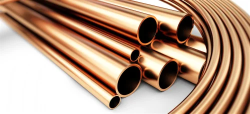
| Name: | Seamless Copper-Nickel Pipe and Tube B466M grade C70400 | ||||||||||
|
Standard Specification for Seamless Copper-Nickel Pipe and Tube This standard is issued under the fixed designation B 466/B 466M; the number immediately following the designation indicates the year of original adoption or, in the case of revision, the year of last revision. A number in parentheses indicates the year of last reapproval. A superscript epsilon (e) indicates an editorial change since the last revision or reapproval. This standard has been approved for use by agencies of the Department of Defense. |
|||||||||||
| Scope | |||||||||||
|
This specification establishes the requirements for seamless copper-nickel pipe and tube in straight lengths, suitable for general engineering purposes. The alloys involved are copper alloys UNS Nos. C70400, C70600, C70620, C71000, C71500, C71520, and C72200. Copper alloys UNS Nos. C70620 and C71520 are intended for product that will be subsequently welded. Units—The values stated in inch-pound or SI units are to be regarded separately as standard. The values in each system are not exact equivalents; therefore, each system shall be used independently of the other. Combining values from the two systems may result in nonconformance with the specification. The following safety hazard caveat pertains only to the test methods described in the Test Methods section of this specification: This standard does not purport to address all of the safety concerns, if any, associated with its use. It is the responsibility of the user of this standard to establish appropriate safety and health practices and determine the applicability of regulatory limitations prior to use. |
|||||||||||
| Materials and Manufacture | |||||||||||
|
Materials—The material of manufacture shall be cast billets of copper alloys UNS Nos. C70400, C70600, C70620, C71000, C71500, C71520, and C72200 as specified in the ordering information and shall be of such quality and sound-ness as to be suitable for processing into finished lengths or coils of tube to meet the properties prescribed herein. Manufacture—The product shall be manufactured by such hot extrusion or piercing and subsequent cold working and annealing as to produce a uniform, seamless wrought structure in the finished product. |
|||||||||||
| Chemical Composition | |||||||||||
|
The material shall conform to the chemical composition requirements prescribed for the copper alloy UNS No. designation specified in the ordering information. These composition limits do not preclude the presence of other elements. By agreements between the manufacturer or supplier and purchaser, limits may be established and analysis required for unnamed elements. For alloys in which copper is specified as “remainder,” copper is the difference between the sum of results for all of the elements determined and 100 %. When all of the elements are determined, the sum of results shall be as shown below: |
|||||||||||
| Copper Alloy UNS No. | Copper Plus Named Elements, % min | ||||||||||
| C70400 | 99.5 | ||||||||||
| Chemical Requirements | |||||||||||
| UNS Nos. | Copper incl Silver | Nickel incl Cobalt | Lead, max | Iron | Zinc, max | Manganese | Sulfur, max | Phosphorus, max | Chromium | Other Named Elements | |
| C70400 | remainder | 4.8 to 6.2 | 0.05 | 1.3 to 1.7 | 1.0 | 0.30 to 0.8 | 0.02 | 0.02 | |||
|
A When the product is for subsequent welding applications, and so specified by the purchaser, zinc shall be 0.50 % max, lead 0.02 % max, and carbon 0.05 % max. B Silicon 0.03 max, titanium 0.03 max. |
|||||||||||
| Temper | |||||||||||
|
Annealed Temper—The product shall be furnished in the O60 (annealed) temper when specified in the ordering information. Drawn Tempers—The product shall be furnished in either the H55 (light drawn), H80 (hard drawn), or HE80 (hard drawn and end annealed) temper when specified in the ordering information. NOTE 1—The H55 (light drawn) temper is used only when product of some stiffness yet capable of being bent is needed. The H80 (hard drawn) temper is used only when there is a need for material as strong as commercially feasible |
|||||||||||
| Mechanical Property Requirements | |||||||||||
|
Tensile Strength Requirements—Product furnished under this specification shall conform to the tensile strength requirements prescribed when tested in accordance with Test Methods E 8 or E 8M. Yield Strength Requirements—Product furnished under this specification shall conform to the yield strength require-ments prescribed when tested in accordance with Test Methods E 8 or E 8M. Rockwell Hardness Requirements—Product furnished under this specification shall conform to the Rockwell hardness requirements prescribed when tested in accordance with Test Methods E 18. The mechanical requirements for tubes of all alloys in the H80 temper are only applicable to the following sizes: |
|||||||||||
| Outside Diameter, in. [mm] | Wall Thickness, in. [mm] | ||||||||||
| Up to 1 [25] incl | 0.020-0.120 [0.5-3.0] incl | ||||||||||
| Over 1-2 [25-50] incl | 0.035-0.180 [0.9-4.5] incl | ||||||||||
| Over 2-4 [50-100] incl | 0.060-0.250 [1.5-6.5] incl | ||||||||||
|
For other sizes in the H80 (hard drawn) temper, the mechanical requirements shall be established by agreement between the manufacturer and the purchaser. The mechanical property requirements for tubes of the HE80 (hard drawn and end annealed) temper shall be established by agreement between the manufacturer or supplier and the purchaser. Tension tests are required to be performed for products having a wall thickness under 0.020 in. [0.5 mm] and an inside diameter of 0.312 [0.8 mm] or smaller. Tension tests for other sizes need not be performed except when indicated in the contract or purchase order at the time of placing the order. |
|||||||||||
| Mechanical Requirements | |||||||||||
| Standard Temper | Former Temper | Copper Alloy UNS Nos. | Tensile Strength, min | Yield Strength,A min | RockwellB Hardness 30 T | ||||||
| ksi | MPa | ksi | MPa | ||||||||
| O60 | Soft annealC | C70400 | 37 | 255 | 12 | 85 | 45 max | ||||
| H55 | Light drawn | C70400 | 40 | 275 | 30 | 205 | 41 to 65 | ||||
| H80 | Hard drawn | C70400 | 45 | 310 | 35 | 240 | 60 min | ||||
|
AAt 0.5 % extension under load. B Rockwell hardness values shall apply only to tube or pipe having a wall thickness of 0.020 in. [0.5 mm] or over and an outside diameter of 5/16 in. [8 mm] or over. For all other tube no Rockwell hardness values shall apply. Rockwell hardness tests shall be made on the inside surface of the tube. When suitable equipment is not available for determining the specified Rockwell hardness, other Rockwell scales and values may be specified subject to agreement between the manufacturer and the purchaser. C Although no minimum grain size is specified, the product must nevertheless have fully recrystallized grain structure. |
|||||||||||
| Nondestructive Test Requirements | |||||||||||
|
Electromagnetic (Eddy Current) Test: Each tube up to and including 3.125-in. [80-mm] nominal outside diameter shall be subjected to an eddy current test. Testing shall follow the procedures of Practice E 243 and the Test Methods section of this specification. The provisions for the determination of “end- effect” in Practice E 243 shall not apply. Hydrostatic Test Alternative—As an alternative to the eddy current test for tubes of diameters above 1.25 in. [32 mm], the manufacturer shall have the option to perform the hydrostatic test to the method in the Test Methods section. The tested tubes, which do not actuate the signaling device of the testing unit, shall be considered as conforming to the requirements of the test. Either notch depth or drilled hole standards shall be used. Notch depth standards shall be 22% of the wall thickness. The sizes of drilled hole standards. Hydrostatic Test: When specified in the contract or purchase order, or as an alternate to the eddy current test for tubes above 1.25 in. [32 mm] in diameter (see 12.1.1.2), each tube shall stand, without showing evidence of leakage, an internal hydrostatic pressure sufficient to produce a fiber stress of 7000 psi [48 MPa] as determined by the following equation for thin hollow cylinders under tension: P = 2St/D – 0.8t) where: P = hydrostatic pressure, psi [MPa]; t = wall thickness of the material, in. [mm]; D = outside diameter of the material, in. [mm]; and S = allowable stress of the material, psi [MPa]. The tube need not be subjected to a pressure gage reading over 1000 psi [7 MPa] unless specifically stipulated in the contract or purchase order. When the hydrostatic test is specified for tubes of less than 0.50 in. [12 mm] in outside diameter and less than 0.060 in. [1.5 mm] in wall thickness, the manufacturer shall have the option to perform either the hydrostatic test to the requirements specified in 12.2 or the pneumatic test to the requirements specified in 12.3. Pneumatic Test—When specified in the contract or purchase order, each tube shall be subjected to a minimum internal air pressure of 60 psig [415 kPa] for 5 s without showing evidence of leakage. |
|||||||||||
| Dimensions, Mass, and Permissible Variations | |||||||||||
|
Wall Thickness Tolerances—The wall thickness tolerances. Diameter Tolerances—The diameter tolerances. Tolerance on distances between parallel surfaces for tubes other than round shall be as agreed between the manufacturer or supplier and purchaser. The following tolerances shall be in accordance with the applicable subsection of Section 5 of the current edition of Specification B 251 or B 251M as follows: |
|||||||||||
| Wall Thickness Tolerances | |||||||||||
| NOTE 1—Maximum Deviation of Any Point—The following tolerances are plus and minus; if tolerances all plus or all minus are desired, double the values given. | |||||||||||
| Wall Thickness, in. [mm] | Outside Diameter,A in [mm] | ||||||||||
|
1/32 to 1/8 [0.80 to 3.2] incl |
Over 1/8 to 5/8 [3.2 to 16] incl |
Over 5/8 to 1 [16 to 25] incl |
Over 1 to 2 [25 to 50] incl |
Over 2 to [3.2 to 16] incl |
Over 1/8 to 5/8 [3.2 to 16] incl |
Over 1/8 to 5/8 [3.2 to 16] incl |
|||||
| Up to 0.017 [.40] incl | 0.0025 [0.064] | 0.0015 [0.38] | 0.002 [0.057] | 0.0025 [0.064] | |||||||
| Over 0.017 to 0.024 [0.040 to 0.60] | 0.004 [0.10] | 0.0025 [0.064] | 0.0025 [0.064] | 0.003 [0.076] | |||||||
| Over 0.024 to 0.034 [0.60 to 0.90] | 0.004 [0.10] | 0.003 [0.076] | 0.003 [0.076] | 0.004 [0.10] | 0.005 [0.013] | ||||||
| Over 0.034 to 0.057 [0.90 to 1.4] | 0.004 [0.10] | 0.004 [0.10] | 0.0045 [0.11] | 0.0045 [0.11] | 0.0065 [0.17] | 0.009 [0.23] | |||||
| Over 0.057 to 0.082 [1.4 to 2.1] incl | 0.0045 [0.11] | 0.005 [0.13] | 0.005 [0.13] | 0.0075 [0.19] | 0.010 [0.25] | 0.013 [0.33] | |||||
| Over 0.082 to 0.119 [2.1 to 3.0] incl | 0.005 [0.13] | 0.0065 [0.17] | 0.0065 [0.17] | 0.009 [0.23] | 0.011 [0.28] | 0.014 [0.36] | |||||
| Over 0.119 to 0.164 [3.0 to 4.2] incl | 0.007 [0.18] | 0.007 [0.18] | 0.0075 [0.19] | 0.010 [0.25] | 0.013 [0.33] | 0.015 [0.38] | |||||
| Over 0.164 to 0.219 [4.2 to 5.5] incl | 0.009 [0.23] | 0.010 [0.25] | 0.012 [0.30] | 0.015 [0.38] | 0.018 [0.46] | ||||||
| Over 0.219 to 0.283 [5.5 to 7.2] incl | 0.012 [0.30] | 0.013 [0.33] | 0.015 [0.38] | 0.018 [0.46] | 0.020 [0.51] | ||||||
| Over 0.283 to 0.379 [7.2 to 9.6] incl | 0.15 [0.38] | 0.018 [0.46] | 0.020 [0.51] | 0.023 [0.58] | |||||||
| Over 0.379 [9.6] | 6B | 6B | 8B | 8B | |||||||
|
A When tube is ordered by outside and inside diameters, the maximum plus and minus deviation of the wall thickness from the nominal at any point shall not exceed the values given in this table by more than 50 %. B Percent of the specified wall thickness expressed to the nearest 0.001 in. [0.025 mm]. |
|||||||||||
| Average DiameterA Tolerances | |||||||||||
| Specified Diameter | Tolerance Applies to | Tolerances, plus and minus,B in. for Tubes of Copper Alloy UNS Nos. C70400, C70600, C70620, C71000, C71500, C71520, and C72200 | Tolerances, plus and minus,B mm for Tubes of Copper Alloy UNS Nos. C70400, C70600, C70620, C71000, C71500, C71520, and C72200 | ||||||||
| in | mm | ||||||||||
| Up to 1/8 , incl | Up to 3.2, incl | inside diameter | 0.003 | 0.076 | |||||||
| Up to 1/8 , incl | Up to 3.2, incl | outside diameter | 0.0025 | 0.064 | |||||||
| Over 1/8 to 5/8 , incl | Over 3.2 to 16, incl | inside or outside | 0.0025 | 0.064 | |||||||
| Over 5/8 to 1, incl | Over 16 to 25, incl | inside or outside | 0.003 | 0.076 | |||||||
| Over 1 to 2, incl | Over 25 to 50, incl | inside or outside | 0.004 | 0.10 | |||||||
| Over 2 to 3, incl | Over 50 to 75, incl | inside or outside | 0.005 | 0.13 | |||||||
| Over 3 to 4, incl | Over 75 to 100, incl | inside or outside | 0.006 | 0.15 | |||||||
| Over 4 to 5, incl | Over 100 to 125, incl | inside or outside | 0.00S | 0.20 | |||||||
| Over 5 to 6, incl | Over 125 to 150, incl | inside or outside | 0.009 | 0.23 | |||||||
| Over 6 to 8, incl | Over 150 to 200, incl | inside or outside | 0.010 | 0.25 | |||||||
| Over 8 to 10, incl | Over 200 to 250, incl | inside or outside | 0.013 | 0.33 | |||||||
|
A The average outside or inside diameter of a tube is the average of the maximum and minimum outside diameters, or of the maximum and minimum inside diameters, whichever is applicable, as determined at any one cross section of the tube. B If tolerances all plus or all minus are desired, double the values given. |
|||||||||||
-
Seamless Copper-Nickel Pipe and Tube B466 grade C72200
-
Seamless Copper-Nickel Pipe and Tube B466 grade C71520
-
Seamless Copper-Nickel Pipe and Tube B466 grade C71500
-
Seamless Copper-Nickel Pipe and Tube B466 grade C71000
-
Seamless Copper-Nickel Pipe and Tube B466M grade C70620

-
Seamless Copper-Nickel Pipe and Tube B466M grade C70600

Mr. Thi
 Email:
theptangiabao@gmail.com
Email:
theptangiabao@gmail.com
|
 Skype:
|
 Hotline/ Zalo/ Wechat:
+84 982 384 688
Hotline/ Zalo/ Wechat:
+84 982 384 688
|

Ms. Hoa
|
Email:
theptangiabao@gmail.com
|
|
Skype:
|
|
Hotline/ Zalo/ Wechat:
+84 982 803 586
|

Ms. Phương
|
Email:
theptangiabao@gmail.com
|
|
Skype:
|
|
Hotline/ Zalo/ Wechat:
+84 971 567 341
|

Ms. Trinh
|
Email:
theptangiabao@gmail.com
|
|
Skype:
|
|
Hotline/ Zalo/ Wechat:
+84 971 567 943
|

Ms. Trân
|
Email:
theptangiabao@gmail.com
|
|
Skype:
|
|
Hotline/ Zalo/ Wechat:
+84 971 567 954
|
![]() HỒ CHÍ MINH CN1
HỒ CHÍ MINH CN1
Trụ Sở Hồ Chí Minh
Address : Số 8 đường số 20, P. Bình Hưng Hoà, Q. Bình Tân, TP. HCM
Phone : +84 982 384 688 - Email : theptangiabao@gmail.com
![]() HỒ CHÍ MINH CN2
HỒ CHÍ MINH CN2
Trụ Sở Hồ Chí Minh
Address : 27/9 đường Tân Thới Nhất 08, Phường Tân Thới Nhất, Q12, TP. HCM, VN
Phone : +84 982 384 688 - Email : theptangiabao@gmail.com
![]() BÀ RỊA - VŨNG TÀU
BÀ RỊA - VŨNG TÀU
Chi Nhánh Bà Rịa - Vũng Tàu
Address : 2597 Đ. Độc Lập, TT. Phú Mỹ, Tân Thành, Bà Rịa - Vũng Tàu, Việt Nam.
Phone : +84 974 618 834 - Email : chinhanhtangiabao@gmail.com
Social network


![]()
![]()


